


308213 17
Service
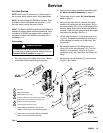
Subplate and Rocker Assemblies
NOTE: Air Valve Repair Kit 222959 is available. Parts
included in the kit are marked with a symbol ({). For
the best results, use all the parts in the kit.
Disassembly
WARNING
To reduce the risk of serious injury whenever you
are instructed to relieve pressure, always follow the
Pressure Relief Procedure on page 10.
1. Stop the pump at the middle of its stroke. Relieve
the pressure before performing any service.
2. Follow the steps under Air Motor Shroud Disas-
sembly on page 11.
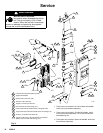
3. Use an allen wrench to remove the six socket
screws (28) holding the air valve (25) to the sub-
plate (23). See Fig. 3 on page 12. Remove the air
valve.
NOTE: To replace or service the air valve, refer to
pages 11–16.
4. Remove the gasket (26) and the two seals (27).
Inspect these parts for wear or damage.
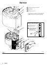
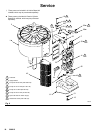
5. Remove the two screws (13) and washers (51)
holding the bottom cover (61) to the bottom rocker
arm cover (62). See Fig. 9.
6. Remove the pad (63, see Fig. 3 on page 12) from
the top rocker assembly. Hold the stud (30) with a
wrench while unscrewing the nut (33). Pull the stud
(30) out and disassemble the rocker assembly.
Push the sleeve (31) out of the rocker arm (29).
Inspect the rocker arm, sleeve, and bearings (32)
for wear.
7. Disassemble the bottom rocker assembly as
explained in step 6.
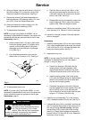
8. Using a 17 mm box wrench, remove the capscrew
(43) and gasket (47) holding the exhaust manifold
(45) to the subplate (23). Remove the two liners
(44) from the cavities in the manifold. Check that
the vertical slot (V) in the manifold is clear of dirt or
blockage; clean with a brush or compressed air.
See Fig. 9.
9. Using an allen wrench, unscrew the eight socket
screws (41) holding the subplate (23) to the cylin-
der (1). Remove the subplate and the gasket (24).
Inspect these parts for wear or damage.
10. Remove the two screws (42), the top rod fitting
(20), and the push rod (19) from the motor cap (2).
Using an o-ring pick, pull out the seal (21). Inspect
these parts for wear. Repeat for the bottom push
rod assembly.
Reassembly
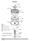
1. Lubricate the seal (21{) and insert it in the motor
cap (2) with the lips facing into the cap. Install
the rod fitting (20{). Grease the end of the push
rod (19) and insert it in the fitting. Apply thread
sealant and torque the screws (42) to 2–3 NSm
(20–30 in-lb). Repeat for the bottom push rod
assembly. See Fig. 9.
2. Place the gasket (24) on the back side of the
subplate (23), aligning the holes in both parts. With
the air inlet port (P) facing up, install the subplate
on the cylinder (1) with the eight socket screws
(41). Torque to 10–12 NSm (90–110 in-lb).
3. Install the two liners (44) in the cavities of the
exhaust manifold (45). Attach the manifold to the
subplate with the gasket (47) and capscrew (43),
using a 17 mm box wrench. Torque to 24–27 NSm
(18–20 ft-lb).
4. Lubricate the sleeve (31) and two bearings (32)
and install them in the rocker arm (29). Position
the rocker arm between the top flanges of the
subplate (23).
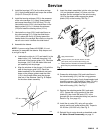
5. Note that the rocker arm cover (62) has two tabs
that are off-center. Install the cover so the end with
the two tabs is toward the outside of the subplate
(see Fig. 9). Insert the stud (30) through the cover
and rocker arm, then install the nut (33). Torque to
22–23 NSm (195–205 in-lb). Replace the rocker
arm cover pad (63, see Fig. 3 on page 12).
6. Assemble the bottom rocker assembly as ex-
plained in steps 4 and 5. Install the bottom cover
(61) and secure to the rocker arm cover with the
two screws (13) and washers (51).
7. Install the two seals (27{) and the gasket (26{).
See the Detail in Fig. 3 on page 12.
8. Install the air valve (25), using a 6 mm allen
wrench and six socket screws (28). Torque to
22–23 NSm (195–205 in-lb).
9. Follow the steps under Air Motor Shroud Reas-
sembly on page 11.