


12
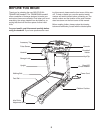
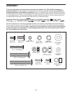
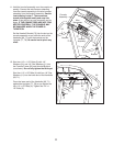
16. Make sure that all parts are properly tightened before you use the treadmill. Note: Extra hardware may
be included. Keep the included hex keys in a secure place; one of the hex keys is used to adjust the walking
belt (see page 21). To protect the floor or carpet, place a mat under the treadmill.
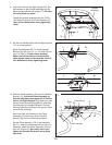
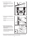
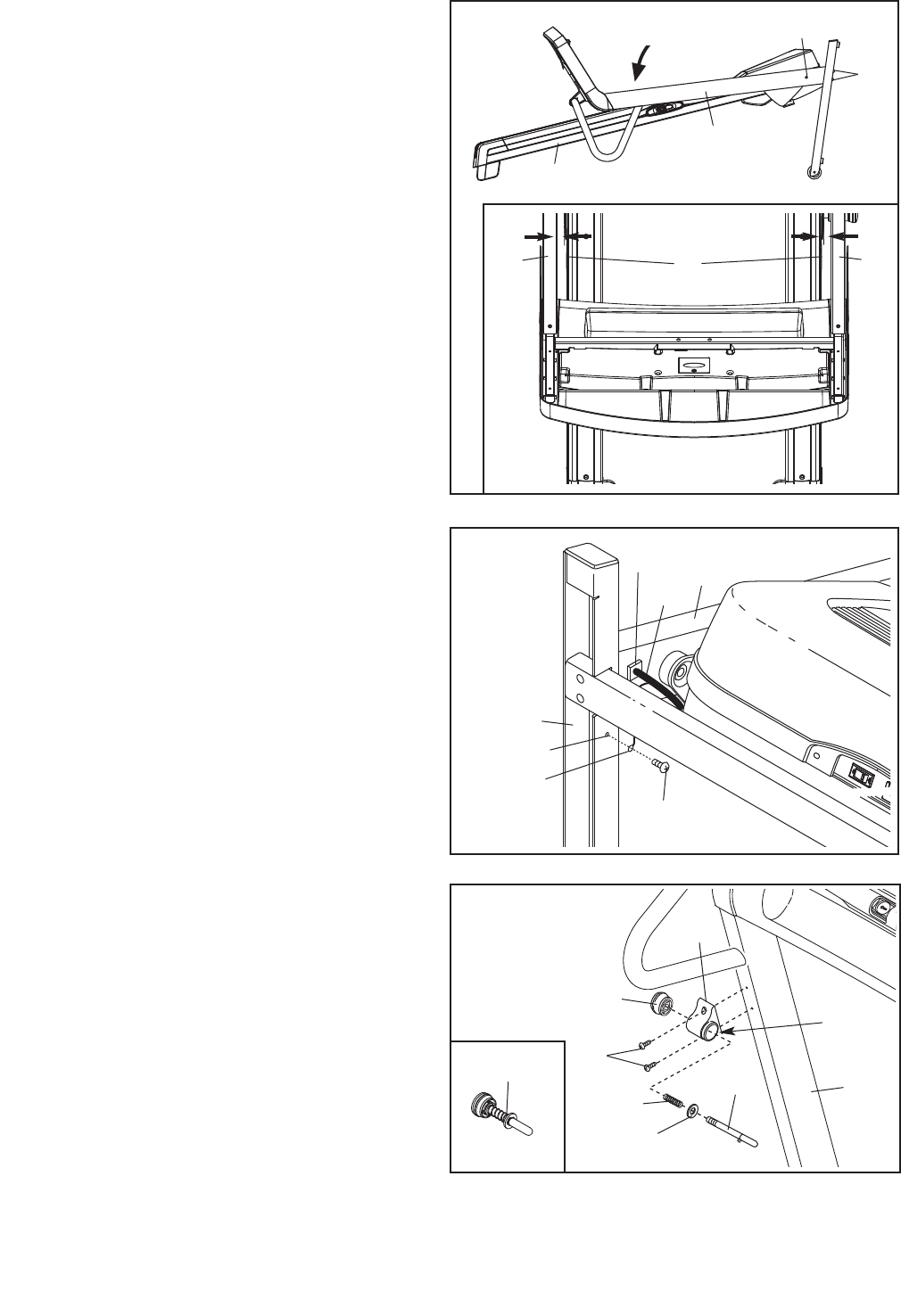
15. Attach the Latch Housing (76) to the Left
Upright (77) with two #8 x 3/4" Screws (7).
Make sure that the large hole in the Latch
Housing is on the side shown. Do not over-
tighten the Screws.
Locate the Latch Pin Assembly (75). Remove
the knob from the pin. Make sure that the collar
and the spring are on the pin as shown. Insert
the pin into the Latch Housing (76), and tighten
the knob back onto the pin.
7
76
77
Large
Hole
15
Knob
Pin
Collar
Spring
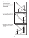
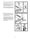
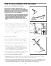
13. Lower the Uprights (77, 78) as shown.
See the inset drawing. Position the Uprights
(
77, 78) so that the Frame (55) is centered be-
tween the Uprights.
Firmly tighten the 3/8" x 2 1/2" Bolt (1) and then
tighten the 3/8" x 2 1/4" Bolts (8) on each side of
the treadmill. Do not overtighten the 3/8" x 2
1/2" Bolts.
78
77, 78
1
5
5
55
77
View from Above
Side View
13
8
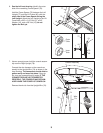
14. Attach the ground wire on the Upright Wire (74)
to the indicated hole in the Base (85) with a #8 x
1/2" Screw (12).
Press the indicated Grommet (21) into the Right
Upright (78).
Raise the Right Upright (78) and the Left Upright
(not shown).
85
74
78
14
12
Ground
Wire
21
Hole
75