


9
3
10
78
75
104
110
78
83
1
1
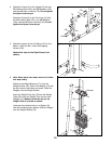
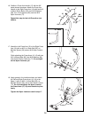
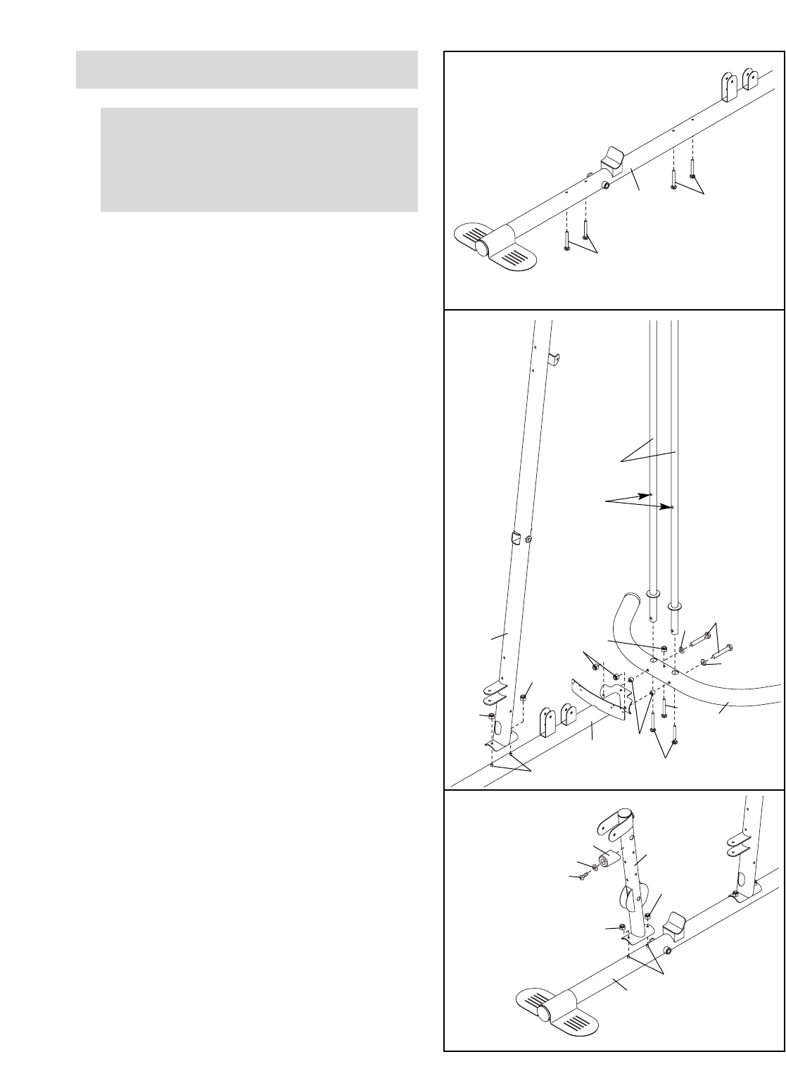
3. Attach the Front Leg (10) to the Base (1) with the
two M8 x 75mm Carriage Bolts (83) and two M8
Nylon Locknuts (78). Do not tighten the Nylon
Locknuts yet.
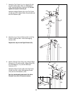
Attach the Leg Lever Bumper (75) to the Front
Leg (10) with an M4 x 16mm Self-tapping Screw
(110) and an M4 Washer (104). Make sure that
the end of the Leg Lever Bumper is pointing
upward.
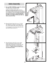
1.
Insert four M8 x 75mm Carriage Bolts (83) up
through the Base (1). Note: It may be helpful to
place a piece of tape over each Carriage Bolt
head to hold it in place.
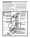
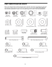
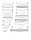
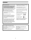
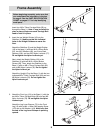
Before beginning assembly, make sure that
you understand the information in the box
on page 8. See the PART IDENTIFICATION
CHART on pages 5–7 for help identifying
small parts.
Frame Assembly
83
83
1
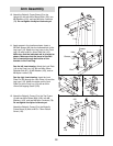
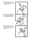
2. Insert the two Weight Guides (18) into the
Stabilizer (3). Make sure that the indicated
holes in the Weight Guides are nearer the
floor.
Attach the Stabilizer (3) and the Weight Guides
(18) to the base (1) with two M10 x 85mm Bolts
(81), two M10 Washers (80), two 21mm Steel
Spacers (108), and two M10 Nylon Locknuts (77).
Do not tighten the Nylon Locknuts yet.
Next, attach the Weight Guides (18) to the
Stabilizer (3) with two M10 x 20mm Button
Screws (96). Then, attach the Stabilizer to the
Base (1) with an M8 x 75mm Carriage Bolt (83)
and an M8 Nylon Locknut (78). Do not tighten
the Nylon Locknut yet.
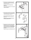
Attach the Upright (2) to the Base (1) with the two
indicated M8 x 75mm Carriage Bolts (83) and two
M8 Nylon Locknuts (78). Do not tighten the
Nylon Locknuts yet.
2
1
18
81
80
80
108
78
78
83
83
96
78
2
3
77
Holes