14
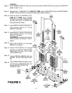
FIGURE 2
8
CENTER
BASE TUBE
(B)
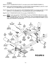
Step 8.
Step 9.
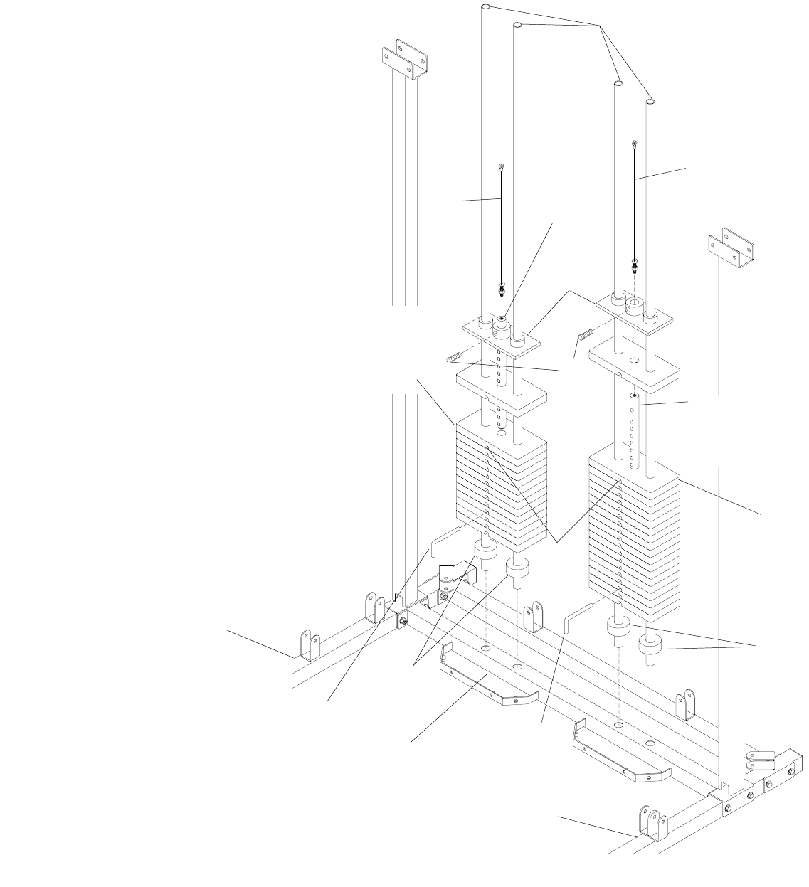
Slide RUBBER DONUTS (82) onto one end of each GUIDE ROD (9) and insert into CENTER
BASE TUBE “B” (8).
Slide a total of 14 WEIGHTS (79), ONE AT A TIME, down GUIDE RODS (9) on the RIGHT BASE
BEAM (1) side, with SLOT on bottom and facing forward as shown.
Slide the other 19 WEIGHTS (79),
ONE AT A TIME, down GUIDE
RODS (9) on the LEFT BASE BEAM
(6) side, with SLOT on bottom and
facing forward as shown.
Insert WEIGHT SELECTOR ROD “A”
(42) through center of 14 high
WEIGHT (79) stack.
Insert WEIGHT SELECTOR ROD “B”
(43) through center of 19 high
WEIGHT (79) stack.
WARNING: Someone will need to
hold this stack until Step 21 is com-
pleted.
Slide TOP PLATES (77) onto both
WEIGHT (79) stacks.
Fasten TOP PLATES (77) through
top hole of WEIGHT SELECTOR
RODS (42 & 43) with 7/16” ALLEN
CAP SCREW (78).
Thread PRESS CABLES (55) into
WEIGHT SELECTOR RODS (42 &
43).
Insert PRESS BAR PIN (80) into de-
sired SLOT in WEIGHTS (79) and
through WEIGHT SELECTOR
RODS (42 & 43).
Step 10.
Step 11.
Step 12.
Step 13.
Step 14.
Step 15.
Step 16.
82
RUBBER
DONUT
9
GUIDE
ROD
1
RIGHT
BASE
BEAM
6
LEFT BASE
BEAM
77
TOP
PLATE
42
WEIGHT
SELECTOR
ROD
“A”
79
WEIGHT
(19 total)
SLOT
80
PRESS
BAR PIN
FIGURE 2
80
PRESS
BAR PIN
78
7/16”
ALLEN
CAP
SCREW
43
WEIGHT
SELECTOR
ROD
“B”
82
RUBBER
DONUT
79
WEIGHT
(14 total)
55
PRESS
CABLE
55
PRESS
CABLE


