


ENG
4
Special tool
Front
LR
Brake button
cable
Cable from the
steering post
Connection cable
Seat base
End cap
Stopper
Console
Cable
connecter
Steering post
Bracket
Brake button
Steering unit
Connection cable
Seat rail
Seat slide adjustment lever
Seat handle
installation
screws
Flat washer
Nut
Installation angle
Seat cushion A installation screw/flat washer
Seat cushion A installation screw
Flat washer
Seat cushion A
R washer
Seat cushion B installation screw
Seat cushion B
Tapping
screw
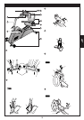
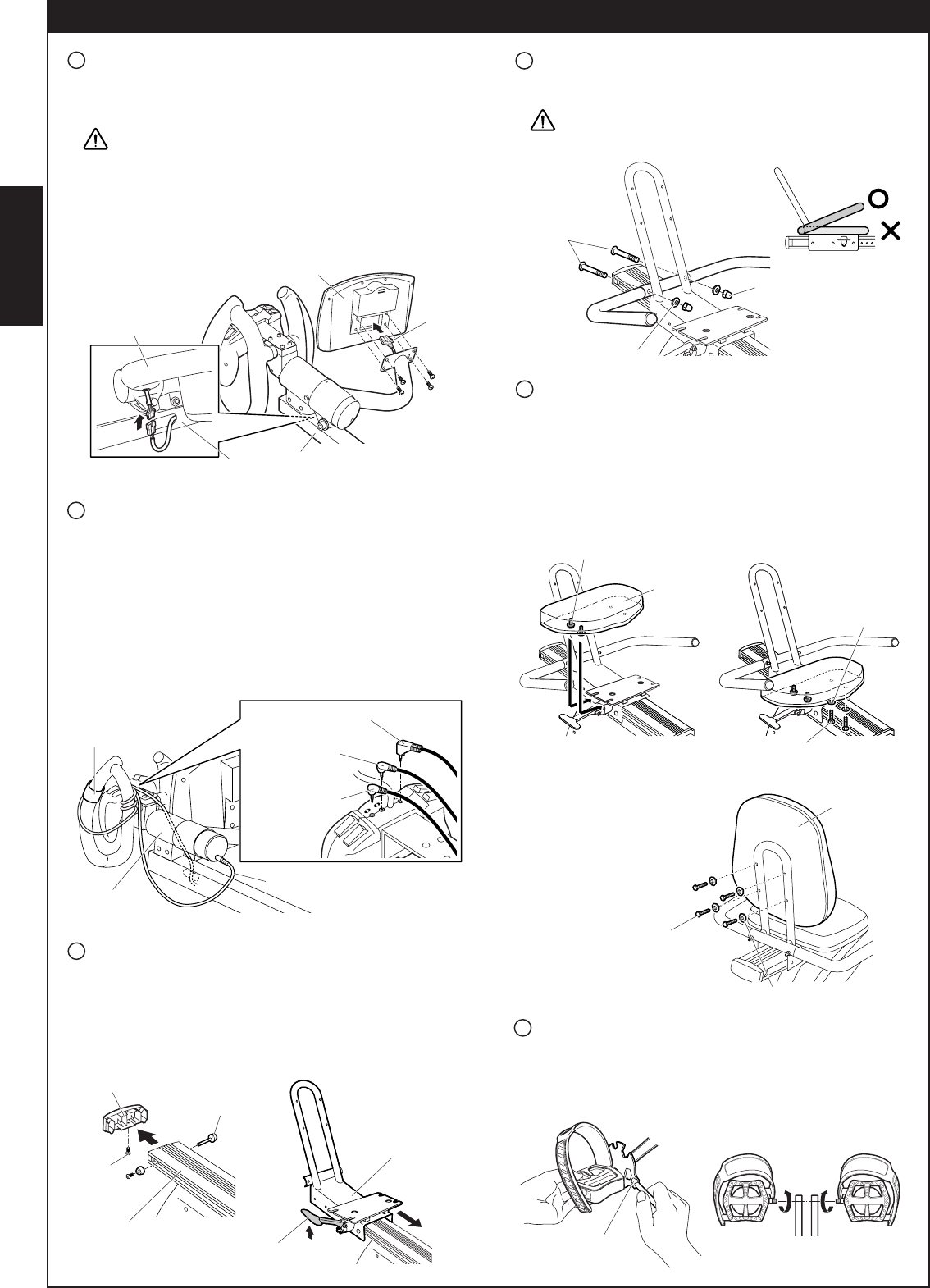
How to assemble GBF PRO RECUMBENT BIKE (2)
12
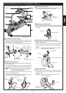
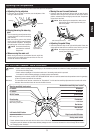
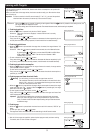
Installing the pedals
• Use the provided special tool to securely fasten the pedals to the
crank, as shown in the figure.
• Be sure to identify R and L of the pedal with the engraved mark.
• Fasten clockwise the R pedal, and counterclockwise the L pedal.
8
Connecting the controller
• Insert the speed sensor cable plug (light blue) which extends from
the steering post into the “S” jack on the controller.
• Install the brake button onto the steering assembly. Insert the cable
plug (yellow) into the “B” jack on the controller.
Important Wind excess brake button cord around the steering
assembly.
• Insert the connection cable plug into the “H” jack on the control-
ler. Insert the straight plug on the other end of the cable into the
jack on the bottom of the steering unit.
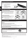
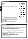
7
Installing the console
• Remove the 4 screws on the back of the console.
• Insert the cable connector which extends from the bracket into
the cable inlet on the back of the console.
Caution Insert the cable connector firmly as far as it will
go. If it is not inserted properly and the contact is
poor, the console will not function.
• Secure the console to the bracket with the removed screws.
• Attach the connector on the steering post to that on the bracket.
Important Conceal the excess cord inside the steering post.
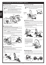
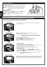
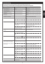
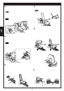
9
Installing the seat base
• Remove the tapping screw from the end cap and then remove the
end cap from the back end of the seat rail.
Remove the stopper from the side of the rail.
• Insert the main unit rail while raising the seat slide adjustment
lever.
• Replace the stopper and end cap in their original positions.
10
Installing the seat handle
• Place the seat handle in position on the rear of the seat base and
securely tighten the “seat handle installation screw set” (2 screws).
Caution Make sure to install the seat handle with the ends
of the handle pointing upward.
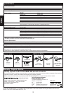
11
Installing the seat cushion
• Install the two “seat cushion A installation screws” on either side
of the back of the seat cushion A (seat) and temporarily tighten
the two screws.
• Secure the side of the cushion on which the screws were tempo-
rarily tightened to the top of the seat base.
• Install the remaining two screws and tighten all four screws to
securely fasten the cushion.
• Place the seat cushion B
(backrest) in position with
the screw holes on the back
of the seat base aligned; se-
curely tighten the “seat cush-
ion B installation screw set”
(4 screws).