


4
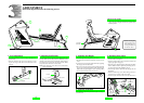
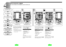
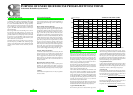
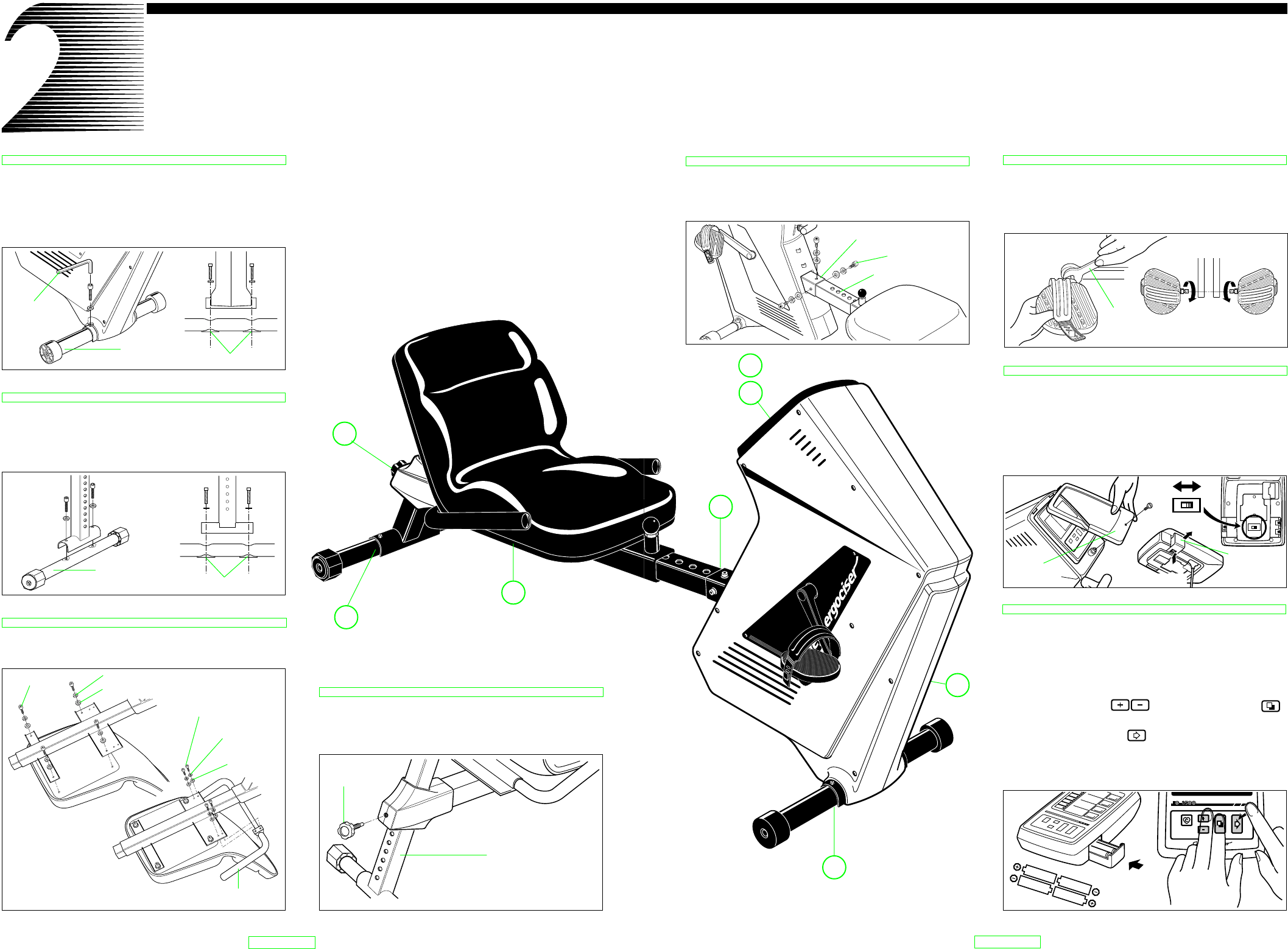
1. Mounting Front Leg
• Remove the leg plate from the main unit.
• Place the front leg (with casters) under the main unit as
shown in Fig. 1 and fasten screws securely with the hexa-
gon wrench making sure nuts locate at the bottom of the
leg.
2. Mounting Rear Leg
Place the rear leg (with level adjuster) under the rear sup-
port pipe as shown in Fig. 2 and fasten screws securely
with the hexagon wrench making sure nuts locate at the
bottom of the leg.
3. Mounting Seat and Handlebar
Mount the seat to the seat pipe using the large screws and
the handlebar using the small ones.
4. Assembling Rear Frame
• Loosen and remove the seat height lock knob.
• Insert the rear support pipe into the socket of seat pipe.
Select any height and tighten the knob.
LET'S ASSEMBLE
2
3
4
Assemble the main unit under the following process.
Fig. 1
nuts
hexagon
wrench
1
3
7
8
6
4
2
5
Fig. 2
nuts
Fig. 4
Fig. 3
handlebar
seat height
lock knob
rear support pipe
flat washer
small screws
spring washer
rear leg
(with level adjuster)
front leg
(with casters)
large screws
spring washer
flat washer
5
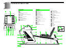
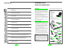
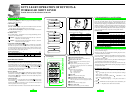
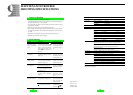
8. Loading (Replacing) Battery
• Load batteries (AA sizex4) in the battery case, making
sure the polarity + or – is right as shown in Fig. 9. Insert
the case into the control unit.
• Replace the control unit in position. Fit the panel cover
and tighten the screw. (Fig. 7)
•
Press the set buttons and the mode button ( )
simultaneously, and keeping these buttons held down
press the advance button to clear all readings. (Fig. 10)
• All LCD segments appear for about 2 seconds and then
disappear. (refer to "Special functions of buttons" in page
10.)
7. Setting Distance Scale
• Remove the control panel cover by loosening the screws
as shown in Fig. 7.
• Remove the control unit and pull out the battery case as
shown in Fig. 8.
• Turn over the control unit and switch to "KM" or "MILE"
to set your desired distance scale.
6. Mounting Pedals
• Attach the pedals to cranks using the spanner wrench
#15.
• Be sure to install the pedal (R) on the right crank and (L)
on the left crank to avoid cross threading.
5. Connecting Inner Pipe
• Remove the 3 screws from the end of the inner pipe.
• Insert the inner pipe into the joint metal of the main unit
and fasten it securely with the 3 screws.
KM
MILE
KM
MILE
R6 : AA
R6 : AA
ADVANCEMODESET
TARGET
PULSE
ON/OFF
1
7
8
5
6
Fig. 9
Fig. 5
(L)
(R)
FRONT
spanner
wrench
#15
Fig. 6
Fig. 10
battery case
Fig. 7
PUSH-OPEN
control
panel cover
Fig. 8
joint metal
screws
inner pipe
EC-35OO