27WPMAN0141 (8/31/01)
CD3538B
1
13
5
2
4
6
7
8
9
9
10
11
7
12
3
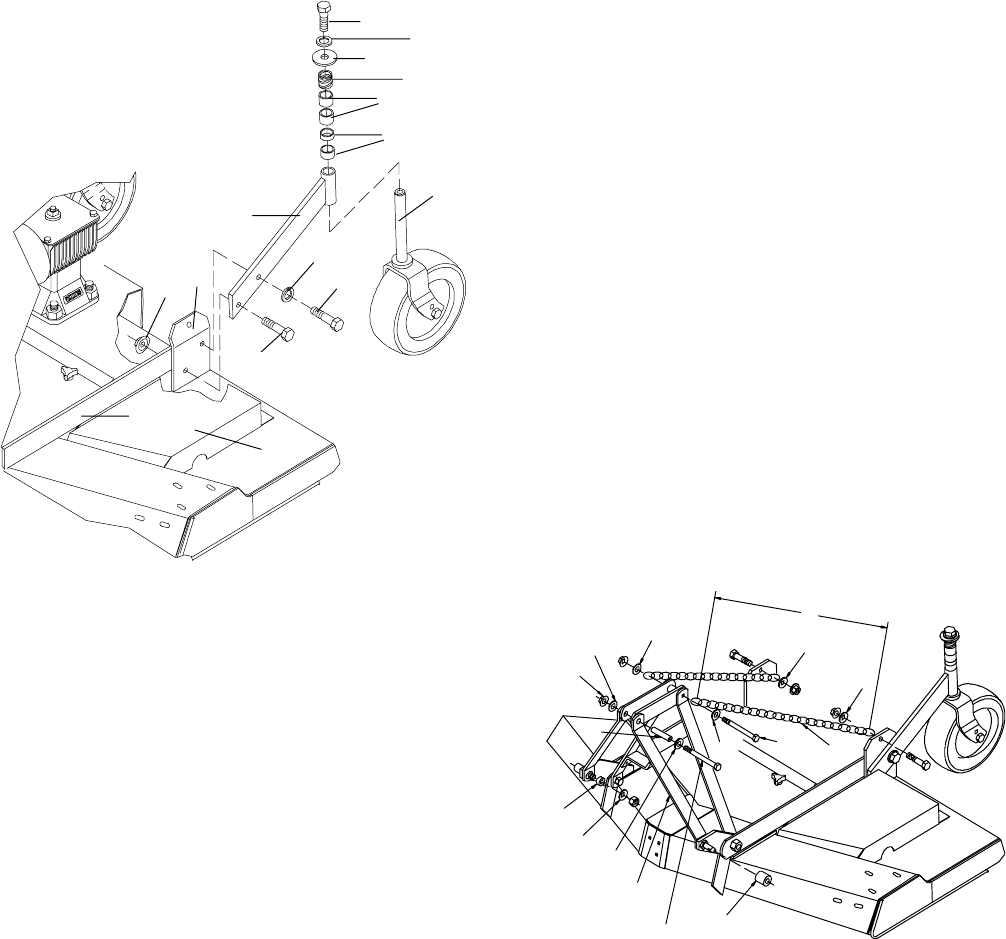
1. Frame rail
2. Frame lug
3. Caster arm
4. 1/2 NC x 1-3/4 Hex head cap screw GR5
5. 1/2 NC Flanged hex locknut
6. 1/2 NC x 2-1/4 Hex head cap screw GR5
7. 1/2” Lockwasher
8. Caster yoke and wheel
9. Height adjustment spacers
10. Spring
11. 1/2” 10 GA Flat washer
12. 1/2 NC x 1-1/4 Hex head cap screw GR5
13. Le
t belt shield
Figure 22. Rear Caster Assembly
Quick Hitch Kit Installation (Option al)
(Figure 23)
Note: This kit allows mower to fit only Cat. 1 standard
ASAE quick hitch.
Attach offset link (1) to mounting pins, using 7/8
sleeve (8) and flat washer (9). Attach upper end of
offset link to pivot link, using 1/2 flat was her (5),
sleeve (6), flange lock nut (7), and 1/2 x 4--3/4 cap
screw.
Remove rear of fset links and replace with chains (2).
Cut to required length. Attach chain to top of A--frame
as shown, using 1/2 x 6 cap screw (4), 1/2 flat washer
(5), and nut.
Attach opposite end of chain (2) to rear mower frame
as shown. Cut chain to 37.5” in length. Va ry length
slightly as desired. Twist chain to make finite
adjustments in length until unit lifts level. Not do
bottom out the drive on front of deck.
IMPORTANT
J F ailure to to follow instructions may result in
damage.
Install sleeve (3) on mounting pins and retain with Klik
pin.
2
3
1
5
6
5
7
5
5
5
8
9
5
A
4
1/2 x 4--3/4 HHCS
M6080
1. Offset Link
2. 38--Link Chain
3. 29/32” x 1-7/16” x 1-1/4” Sleeve
4. 1/2” x 6 Cap Screw
5. 1/2” Flat W asher
6. 1/2” x 3/4” x 3-3/8” Sleeve
7. 1/2” Flange Lock Nut
8. 7/8” Sleeve
9. 7/8” Flat W asher
Figure 23. Quick Hitch Kit Assembly
(Rev. 6/6/2002)


