WPMAN0141 (8/31/01)22
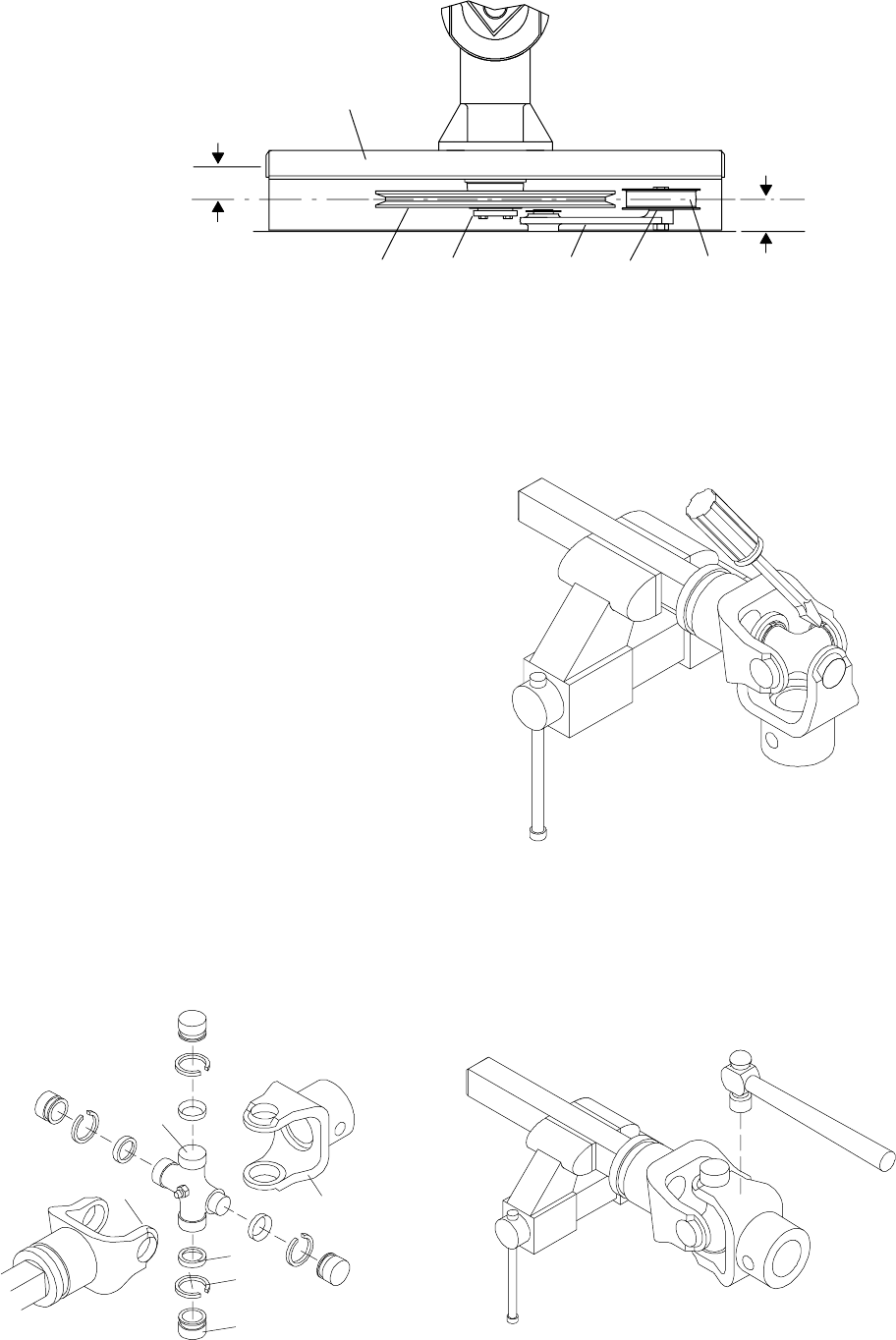
1. Shim gaskets
2. Idler arm
3. Idler pulley
4. Drive pulley
5. Taper lock bushing
6. Gearbox stand
45
2
1
3
6
DIM B
DIM A
CD3548C
Figure 14. Pulley Alignment
Drive Pulley Installation (Figure 14)
Invert gear stand. Install drive pulley and split taper
bushing on vertical gearshaft. Make sure key and
keyways are aligned.
T ighten split taper bushing so dimension “B” (from the
centerline of the drive pulley to the center of the
gearbox stand mounting hole) is 1-15/16”. This is a
reference dimension and may require adjustment.
When gear stand is installed on mower, d imension “A”
(from the top of the mower deck to the centerline of the
drive pulley) must be 1-27/32” (plus or minus 1/32”).
This is a critical d imension and must be held. Remove
gear stand and adjust drive pulley as needed. Add or
subtract shim washers under idler pulley to align with
drive pulley . T ighten gear stand hardware.
Fill gearbox half full of SAE 90W gear lube. Check
level after waiting five minutes to permit lube to work
through bearings and add lube, if necessary, until it is
half full.
Attach driveline to gearbox with shear bolt. Replace
snap ring. Replace driveline shielding and secure with
shield retainers.
UNIVERSAL JOINT REPAIR
CD1402
6
1
2
3
4
5
1. Yoke
2. Journal cross
3. Seal
4. Snap ring
5. Cup and
bearings
6. Yoke
Figure 15. U-Joint Exploded View
U-Joint Disassembly
1. Remove snap rings from inside of yokes in four
locations as shown in Figure 16.
CD1384
Figure 16
2. W ith snap rings removed, support drive in vise,
hold yoke in hand and tap on yoke to drive cup up
out of yoke. See Figure 17.
CD1386
Figure 17


