PDS • User’s Guide 21
3. Installation
Signal Installation
páÖå~ä=fåëí~ää~íáçå
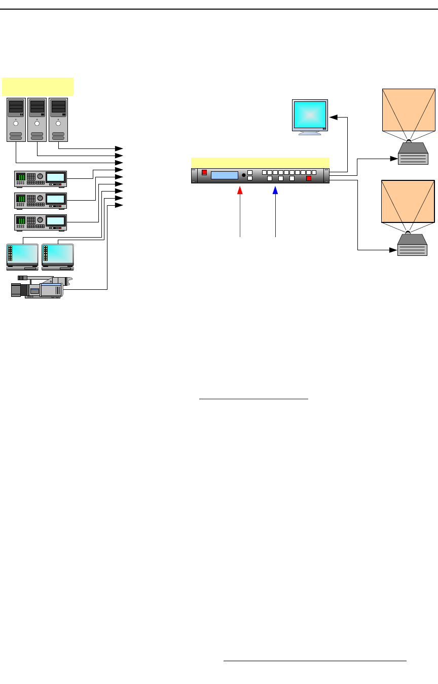
The figure below illustrates a sample PDS system. Use this figure for reference during the
signal installation process.
Figure 3-1. PDS System Diagram (sample)
Use the following steps to install signals to/from the PDS:
1. Input connections — any combination of inputs can be connected.
a. As required, connect analog RGBHV sources to Inputs 1 through 4.
Refer to the “Format Connection Table” section on page 22 for a table
of analog input combinations.
b. As required, connect DVI sources to Inputs 5 through 8 (using the
connector’s digital pins). Inputs 7 and 8 are not available on PDS-701.
c. As required, connect analog sources to Inputs 5 through 8 (using the
connector’s analog pins). A customer-supplied breakout cable or DVI to
HD-15 adapter is required for this connection. Inputs 7 and 8 are not
available on PDS-701.
d. As required, connect an HD-SDI or SD-SDI source to Input SDI.
2. Output connections — up to three outputs can be connected:
a. If you are connecting the PDS to a digital projector (for example) or other
target device, connect the DVI Output to the projector’s DVI input.
b. If you are connecting the PDS to an analog projector (for example) or
other target device, connect the Analog (HD-15) Output to the
projector’s analog input.
c. If you are connecting the PDS 902 to a Preview monitor, connect the
Preview DVI or Analog (HD-15) Output to the monitor.
Inputs 1 - 4 (Analog)
Inputs 5 - 8 (DVI) **
Input SDI
Sample Source Input
Devices
Program
Ethernet
Serial
Preview
PDS-xxx
Sample Source Input
Devices
*
* Preview output not available on PDS 701 or 901
** Inputs 7 and 8 not available on PDS 701
Analog
DVI
Program


