7
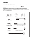
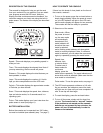
7. Finish attaching the Handlebar (57) to the
Handlebar Post (3) with two more M8 x 15mm
Button Screws (53) and two more M8 x 19mm
Washers (54). Tighten all four Hex Head Screws.
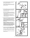
The Console (33) requires two ÒAAÓ batteries (not
included)Ñalkaline batteries are recommended.
Refer to the inset drawing. Open the battery cover
(not shown) on the back of the Console. Press two
batteries into the battery clip. Make sure that the
negative (Ð) ends of the batteries are touching
the springs. Close the battery cover.
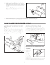
5. Attach the Console (33) to the Handlebar Post (3)
with four #8 x 1/2Ó Screws (43). Be careful to avoid
pinching the wires and cables.
Next, press the Resistance Knob (32) onto the
Resistance Control (31). Attach the Resistance
Knob with the Knob Screw (71). Press the Knob
Cover (72) onto the Resistance Knob.
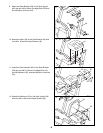
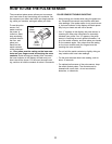
8. Attach the Seat Upright (64) to the Seat Frame (2)
with four M8 x 55mm Carriage Bolts (11) and four
M8 Nylon Locknuts (55). Note: It may be helpful to
tip the exercise cycle on its side to attach the Seat
Upright.
64
55
55
2
53
53
3
5
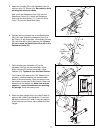
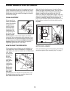
6. Connect the long console wire to the Reed Switch
Wire (42). Next, attach the Handlebar Post (3) to
the Frame (1) with three M8 x 15mm Button Screws
(53) and three M8 x 19mm Washers (54). Be care-
ful not to pinch the Reed Switch Wire (42) or the
Resistance Cable (70).
6
7
57
33
54
54
Battery Clip
Batteries
Long
Console
Wire
8
11
11
42
53
3
1
33
3
71
72
32
43
31
54
53
54
70


