


32
99
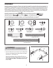
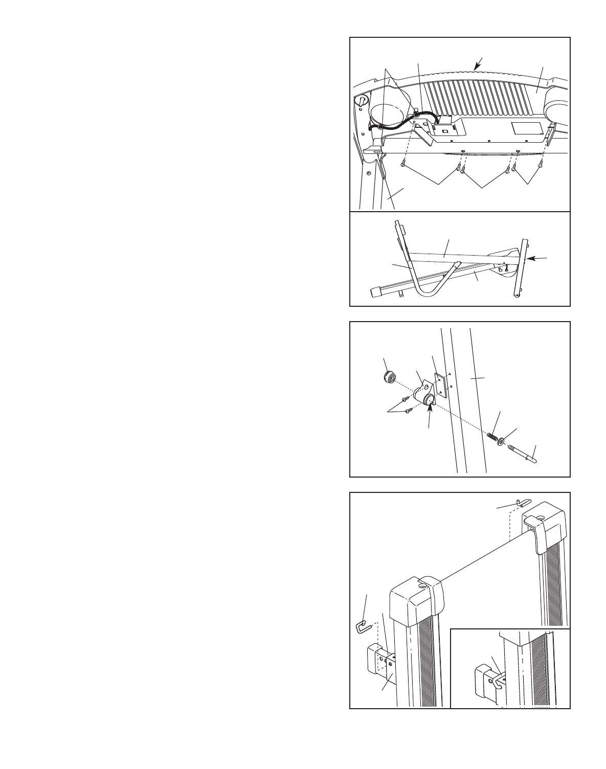
Pin
Collar
Spring
77
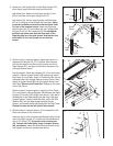
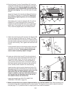
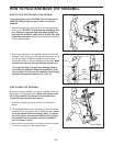
11. Attach the Latch Housing (25) and the Latch Spacer (99)
to the Left Upright (32) with two 3/4” Screws (77). Next,
remove the latch knob from the latch pin. Make sure that
the collar and the spring are on the pin, and insert the pin
into the Latch Housing. Then, tighten the knob back onto
the pin.
Lift the treadmill frame to the storage position (see page
14). Make sure that the frame is centred between the
Handrails (not shown). Firmly tighten the bolts and
screws used in assembly steps 3 through 7.
13. Make sure that all parts are properly tightened before you use the treadmill. Note: Extra hardware may
be included. Keep the included hex keys in a secure place. The large hex key is used to adjust the walking
belt (see page 17). To protect the floor or carpet, place a mat under the treadmill.
1
0
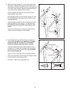
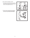
10. Set the Console (2) on the Console Base (45). Insert the
excess Wire Harness (53) into the large hole in the side of
t
he Right Handrail (5). S
ecurely tighten the plastic ties
on the bottom of the Console Base to prevent the Wire
H
arness from slipping.
T
hen, cut off the ends of the plas-
tic ties.
A
ttach the Console (2) to the Console Base (45) with four
3/4” Screws (77) and two 1/2” Screws (92).
Start all six
Screws before tightening them; do not overtighten
the Screws.
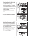
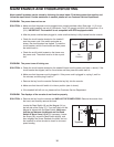
See drawing 10a. Lower the Uprights (32, 37) until the
Handrails (4, 5) are touching the floor. Position the
Uprights so that the treadmill Frame (21) is centred be-
tween them. Firmly tighten the four Upright Bolts (28).
Then, raise the Uprights back to the vertical position.
11
77
92
5
77
45
53
2
Ties
Large
Hole
Knob
25
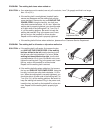
12. Insert one of the Incline Legs (47) into the right side of
the Frame (21) as shown, and adjust the Incline Leg to
the desired height. (Note: The Incline Leg can be ad-
justed to any of four positions to vary the intensity of
your exercise.) Next, fully insert an Incline Pin (46) into
the Frame and the Incline Leg, and turn the Incline Pin
to the “locked” position shown in the inset drawing.
Insert the other Incline Leg (not shown) and Incline Pin
(46) into the left side of the Frame (21) in the same way.
CAUTION: Before using the treadmill, make sure that
both Incline Pins are fully inserted at the same
height. In addition, make sure that both incline pins
are inserted from the direction shown. Do not use
the treadmill without the Incline Pins.
Lower the treadmill (see HOW TO LOWER THE
TREADMILL FOR USE on page 15).
47
21
46
46
46
12
10
10a
28
32, 37
4, 5
21