


9
12
13a
13b
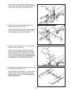
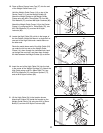
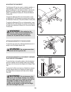
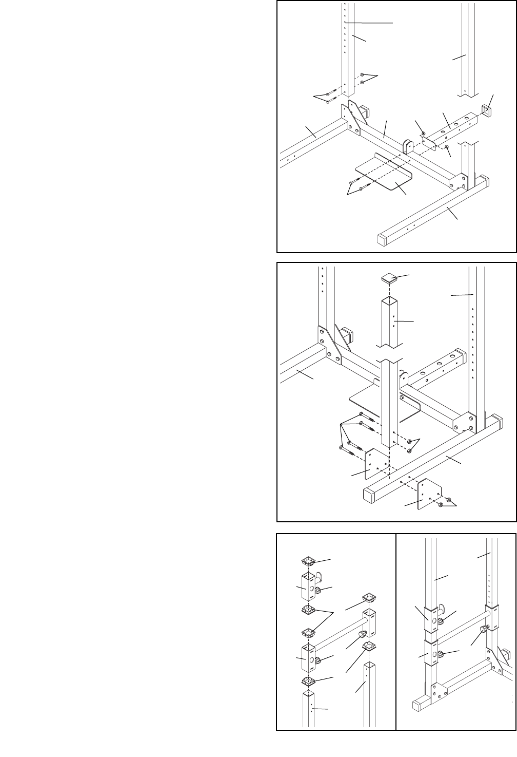
13. Refer to drawing 13a. Press six Square Bushings
(21) into the Right Weight Rest (19) and the Right
Weight Spotter (20) as shown. Pull out the
Adjustment Knobs (22) and slide the Right Weight
Spotter and the Right Weight Rest down over the
right Uprights (7, 8) as indicated.
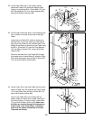
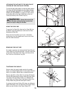
Refer to drawing 13b. Secure the Right Weight
Spotter (20) and the Right Weight Rest (19) to the
right Uprights (7, 8) by tightening each of the three
Adjustment Knobs (22) into one of the adjustment
holes in the Uprights.
Assemble the Left Weight Spotter (not shown) and
Left Weight Rest (not shown) on the left Uprights
(7, 8) in the same manner. Make sure both Weight
Spotters and both Weight Rests are at the same
height.
11
3
1
70
68
68
21
21
22
22
7
7
8
8
22
22
20
20
19
19
6
6
7
8
57
1
2
570
70
68
68
68
4
3
56
8
Adjustment
Holes
8
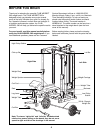
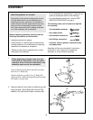
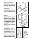
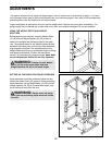
11. Identify the two Rear Uprights (8), which are slightly
shorter than the Front Uprights (not shown).
Attach the Rear Uprights to the Left and Right
Bases (1, 3) using four M10 x 78mm Bolts (70) and
four M10 Nylon Locknuts (68). Do not tighten the
Nylon Locknuts yet. Make sure the Uprights are
oriented exactly as shown, with the adjustment
holes on the indicated side near the bottom.
Press a 60mm Square Outer Cap (56) onto the end
of the Weight Guide Base (4).
Attach the Foot Plate (5) and the Weight Guide
Base (4) to the Center Base (2), as shown, using
two M10 x 78mm Bolts (70) and two M10 Nylon
Locknuts (68). Do not tighten the Nylon Locknuts
yet.
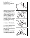
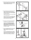
12. Tap a 60mm Square Inner Cap (57) into each of the
Front Uprights (7).
Attach one of the Front Uprights (7) and two Joint
Plates (6) to the Left Base (3) using four M10 x
78mm Bolts (70) and four M10 Nylon Locknuts (68).
Make sure the Front Upright is oriented so that
the holes on the bottom of the Front Upright and
the holes in the Joint Plates line up. If they do
not line up, turn the Front Upright upside-down.
Do not tighten the Nylon Locknuts yet. Make
sure the Front Upright is turned so the adjust-
ment holes are facing the Rear Upright (8) and
so the number decals on the Front Uprights are
facing each other.
Attach the other Front Upright (7, not shown) and
two Joint Plates (6, not shown) to the Right Base
(1) in the same manner.
21