


4
ASSEMBLY
1
2
27
11
11
1
5
78
78
3
5
51
51
11
4
1
Before beginning assembly, carefully read the
following information and instructions:
• Place all parts of the home gym system in a
cleared area and remove the packing materials;
do not dispose of the packing materials until
assembly is completed.
• The assembly is divided into four stages: 1) frame
assembly, 2) press, squat, and butterfly arm
assembly, 3) cable and pulley assembly, and 4)
seat and backrest assembly. The hardware for
each stage is packaged separately.
• Wait until you begin each assembly stage to open
that parts bag.
• For help identifying the small parts used in
assembly, use the PART IDENTIFICATION
CHART located in the center of this manual.
Note: Some small parts may have been pre-
attached for shipping. If a part is not in the parts
bag, check to see if it has been pre-attached.
• As you assemble the home gym system, be sure
that all parts are oriented as shown in the
drawings.
• Tighten all parts as you assemble them, unless
instructed to do otherwise.
THE FOLLOWING TOOLS (NOT INCLUDED) ARE
REQUIRED FOR ASSEMBLY:
• Two (2) adjustable wrenches
• One (1) standard screwdriver
• One (1) phillips screwdriver
• One (1) rubber mallet
• Lubricant, such as grease or petroleum jelly,
and soapy water will also be needed.
Assembly will be more convenient if you have the
following tools: A socket set, a set of open-end or
closed-end wrenches, or a set of ratchet wrenches.
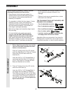
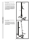
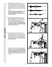
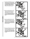
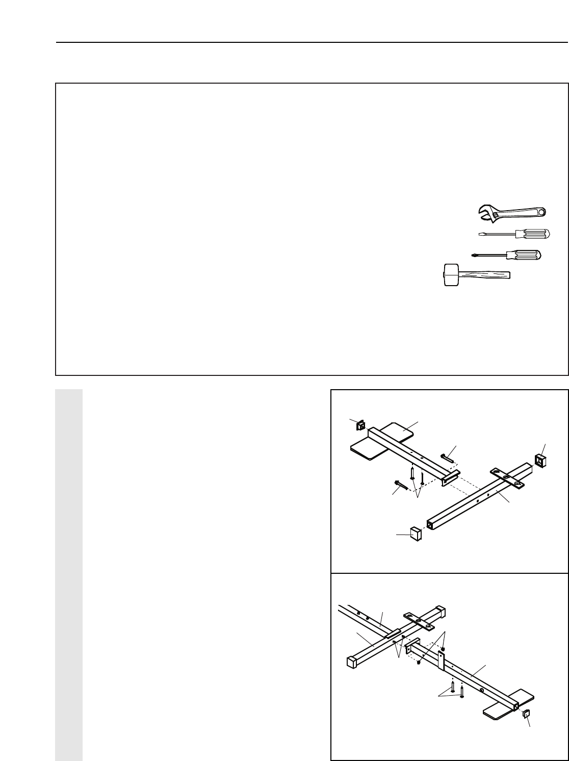
1. Before beginning assembly, be sure that
you have read and understand the infor-
mation in the box above.
Press a 2” Square Inner Cap (27) into the
end of the Rear Base (51). Press a 2” Square
Cover Cap (78) onto each end of the
Stabilizer (5).
Insert two 5/16” x 2 1/2” Carriage Bolts (1)
up through the Rear Base (51). Insert two
5/16” x 2 3/4” Bolts (11) through the Rear
Base and Stabilizer (5) as shown.
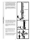
2. Press a 2” Square Inner Cap (27) into the
end of the Front Base (4).
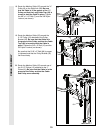
Insert two 5/16” x 2 1/2” Carriage Bolts (1)
up through the Front Base (4). Slide the
Front Base onto the two 5/16” x 2 3/4” Bolts
(11) in the Rear Base (51) and Stabilizer (5).
Hand-tighten two 5/16” Nylon Locknuts (3)
onto the Carriage Bolts. Do not tighten the
Nylon Locknuts yet.
FRAME ASSEMBLY
27