10
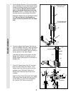
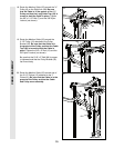
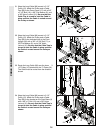
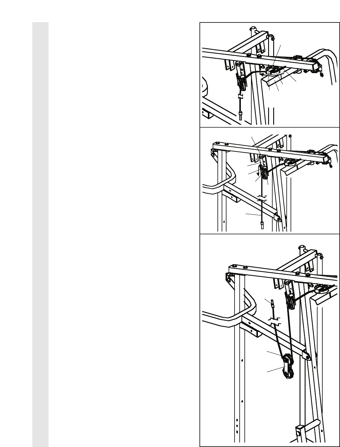
18. Route the Medium Cable (23) around the “V”-
Pulley (6) on the Right Arm (48). Be sure
that the Cable is in the groove of the “V”-
Pulley and that the Long Cable Trap (50) is
turned to hold the Cable in place. Tighten
the 3/8” x 2 1/2” Bolt (7) and the 3/8” Nylon
Locknut (not shown).
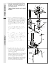
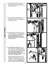
19. Route the Medium Cable (23) around the
3 1/2” Pulley (15) attached to the Pulley
Bracket (20). Be sure that the Cable is in
the groove of the Pulley and that the Cable
Trap (66) is turned to hold the Cable in
place. Tighten the 3/8” x 2” Bolt (12) and the
3/8” Nylon Locknut (not shown).
Be sure that the 5/16” x 5” Bolt (68) is proper-
ly tightened and that the Pulley Bracket (20)
can move freely.
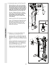
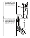
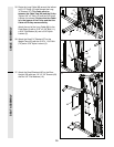
20. Route the Medium Cable (23) around one of
the 3 1/2” Pulleys (15) attached to the “I”
Plates (81). Be sure that the Cable is in the
groove of the Pulley and that the Cable
and Pulley move smoothly.
18
19
20
CABLE ASSEMBLY
23
15
81
50
7
23
66
15
12
20
68
23
48
6


