9
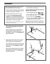
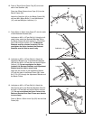
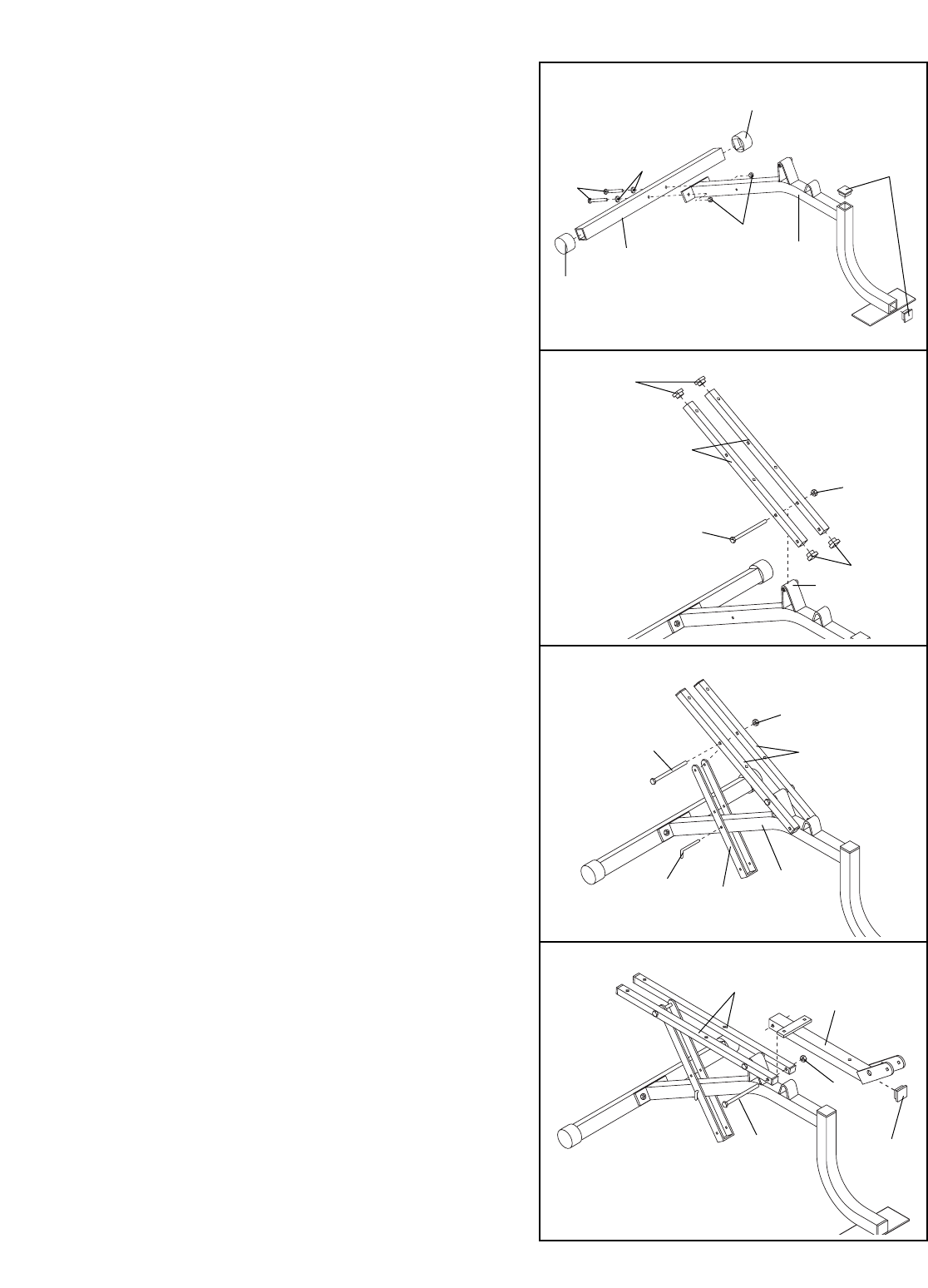
10. Press a 76mm Round Outer Cap (25) onto each
side of the Stabilizer (49).
Press two 50mm Square Inner Caps (21) into the
Bench Frame (39).
Attach the Stabilizer (49) to the Bench Frame (39)
with two M8 x 68mm Bolts (1), two M8 Washers
(15), and two M8 Nylon Locknuts (11).
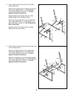
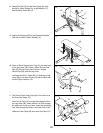
11. Press 20mm x 40mm Inner Caps (27) into the ends
of both Backrest Brackets (38).
Lubricate an M10 x 127mm Bolt (4). Using the indi-
cated holes, attach the Backrest Brackets (38) to
the Bench Frame (39) with the M10 x 127mm Bolt
and an M10 Nylon Locknut (12). The Backrest
Brackets must be oriented as shown. Do not
overtighten the Nylon Locknut; the Backrest
Brackets must be able to move freely.
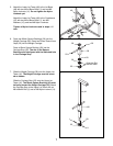
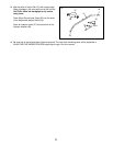
12. Lubricate an M10 x 127mm Bolt (4). Attach the
Adjustment Bracket (51) to the Backrest Brackets
(38) with the M10 x 127mm Bolt and an M10 Nylon
Locknut (12). Do not overtighten the Nylon
Locknut; the Backrest Brackets and Adjustment
Bracket must be able to move freely.
Align one set of holes in the Adjustment Bracket
(51) with the hole in the Bench Frame (39). Insert
the “L”-Pin (50) through the Adjustment Bracket and
the Bench Frame.
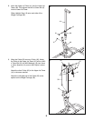
13. Lubricate an M10 x 127mm Bolt (4). Attach the
Seat Frame (44) to the Backrest Brackets (38) with
the M10 x 127mm Bolt and an M10 Nylon Locknut
(12). Do not overtighten the Nylon Locknut; the
Backrest Brackets and Seat Frame must be able
to move freely.
Press a 38mm x 50mm Inner Cap (22) into the Seat
Frame (44).
13
10
21
1
15
1
25
39
27
27
38
Lubricate—4
50
38
39
51
22
44
11
12
49
25
39
12
12
4
Lubricate
38
12
Lubricate
4


