


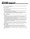

E4100 Assembly
NOTE: During each assembly step, ensure that ALL nuts and bolts are in place and partially threaded in
before completely tightening any ONE bolt.
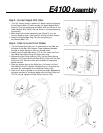
Step 1 • Rear Foot
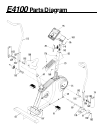
1: Secure the Rear Foot Assembly (62) to the Frame by using the four Rear Foot Attachment Bolts (167).
Step 2 • Seat and Seat Post
1: Slide the Seat Post (65) into the frame seat post receiver tube. The seat post numbers should be
facing the right or seat pin side of the Fitness Cycle.
NOTE: Both nuts in the Seat Clamp should be tightened at the same time, to ensure a proper fit.
2: Attach the Seat (108) to the Seat Post (65) and tighten securely. To avoid scratching the seat post
paint, always hold the the seat pin knob out when adjusting the seat post height.
Step 3 • Console Mast
1: Remove the Top Cap Screws (176) which hold the Top Cap (82) to the frame. Then remove the Top
Cap (82).
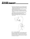
NOTE: DO NOT thread in the Water Bottle Cage Bolts yet. Never slide the Top Cap (82) on or off with
the Waterbottle Cage Bolts threaded in, as they will scratch the paint on the Console Mast (70).
2: Slide the Top Cap (82) over the bottom of the Console Mast (70). The VISION decal on the Console
Mast (70) should be facing forward, away from the rider.
3: Locate the RPM Sensor Wire (96) and the Lower Magnet Shift Cable (143). Holding the Top Cap (82)
and Console Mast (70) above the frame console mast receiver tube, guide the RPM Sensor Wire (96)
and the Lower magnet Cable (143) through the Console Mast (70) while simultaneously sliding
the Console Mast (70) into the receiver tube.
4: Lift the Top Cap (82) up, install the two 38mm-long Console Mast Allen bolts (168) and tighten
securely.
5: Now slide the Top Cap (82) back into place. Make sure that the back end of the Top Cap (82) is
nested fully into the Seat Cap groove. Secure the Top Cap (82) by threading the three Top Cap Screws
back into their holes.
NOTE: Check that there are no large gaps between the Top Cap (82) and the Side Covers.
Step 4 • Console
1: Feed the Upper Magnet Shift Cable (179) into the topmost opening of the Console Mast (70).
2: Plug the RPM Sensor Wire (96) into the Console (95). DO NOT PINCH the RPM Sensor Wire (96)
between the Console (95) and the Console Mast (70). Make sure the cable fits in the slot cut in the
Console Mast Mount.
3: Mount the Console (95) to the Console Mast (70) using the six Console Attachment Phillip Head Bolts
(163).