


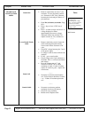
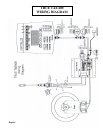
Symptom Probable Cause Corrective Action Recommended Tools
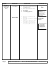
RESISTANCE
MALFUNCTION
600EA
Console Set
Lower Board / Brake
Cable
Brake Coil
Console Cable
• Remove console bolts to access 7-pin
connector. Do not disconnect console
set. Set meter for DC Volts. Measure
between pin 1(red) and pin 5(blue) at 7-
pin connector.
• Enter DA (resistance) test mode. Page
SG-1.
• Press + key to force .9 VDC out of
panel.
• Press + to check voltage at all levels. Is
voltage displayed on meter
approximately the same as voltage
displayed in heart rate window? No-
replace console set. Yes, continue on.
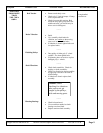
--------
• Remove main body cover & locate the
cable connecting the brake and the
lower control board. Set meter to DC
volts.
• Check DC voltage between pins 2 and 4
of the power supply
• Is voltage is same as shown in heart rate
window?
• If NO – go to console cable.
• Check voltage at the 2-pin connector at
the brake. Press + to increase resistance
and voltage.
• Does the voltage start at 3.7 and
increase to 30 VDC? If no- check
continuity of cable. If cable is broken
replace it, if cable is good – replace the
lower board.
--------
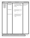
• Set meter to resistance and check the
coil. Coil resistance should be 15 ohms,
+ or – 2 Ohms. If not then replace the
coil.
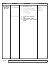
--------
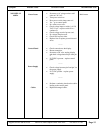
• Set meter to resistance; perform
continuity check on wire harness.
• Check for cross continuity.
• Broken wires? Replace cable.
Note:
You must pedal at least
30 RPM when
p
erforming any voltage
test. You may require the
assistance of another
p
erson when performing
volta
g
e checks.
Multi-meter
Support Services 800-883-8783 Mon-Fri 8:30am-5:00pm Central Time Zone Fax: 636-272-7148
Page 12