


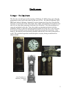

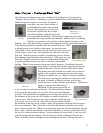
5
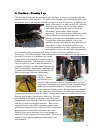
M
y
Drawin
g
(
see attachment C
)
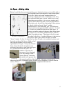
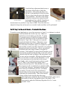
On Paper – Making a Map
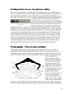
Before I could take the movement entirely apart, it had to be drawn so I would be able to
put it together again with the gears in their proper places.
To do this, I drew circles and numbered them in a
hierarchy to display the order in which they went, then
drew each individual gear to show “which way was up”.
Since there are two plates, it is very easy to put a gear’s
opposite end in the wrong hole, so not only did I have to
know their order, but also the relationship of their pinions
to wheels, which end went “down”, and the
characteristics of each individual gear. The difference
between pinions and gears should be explained. A wheel
is, of course, a toothed disk that drives other gears. A
pinion is a smaller portion of the gear, either in the shape
of a lantern or a cut, smaller wheel that mates with the
wheel of an adjacent gear. The pinion is the driven and
the wheel is the driver. Another difference is that pinions
have fewer “teeth” than a wheel, but they’re called
“leaves” instead. In fact, if a wheel has less than 20 teeth, it is considered a pinion, and
the teeth are then called leaves. Both a wheel
and a pinion together on a steel shaft is
representative of a gear. At any rate, I had to
know where the wheels and pinions were
positioned on each gear, and where each gear
was positioned between the plates. In
addition to drawing the
movement, I also examined
it for any damage I hadn’t
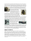
already noticed. One thing
that made itself apparent was
the warped condition of the hand nut. Placing it in a hole on an
otherwise flat block, I pounded it gently flat with a brass hammer so as not to mar the
surface. Thus, I straightened the hand nut.
Bent Hand Nut