


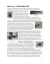
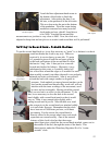
11
rotation of the escape wheel. The lock face is the portion of the pallet that stops an
escape tooth. There are also lift angles on the ends of the pallets (the lift faces) that drive
the pendulum sufficiently to keep the clock running, and are subject to wear (as are the
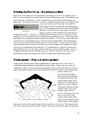
lock faces). My first goal was to measure the lift angles. To do so, I measured the pallets
from the center of the pivot to the mid-point of the pallet thickness. Dividing this by two
gave a value of half of the length of the pallet arm. Knowing that measurement, I drew a
circle with an equal radius and drew a tangent line on that circle. This represented 2
o
of
lift when the pivot of the escape pallets was placed through the center of the circle and
the lift faces were lined up with the tangent line. For clocks with small, light pendulums,
2
o
is an optimum lift angle. The Regulator has a large, heavy pendulum, however, and
1.5 degrees is most desireable for such clocks. To draw a 1.5-degree circle, I divided the
original measurement by two to achieve one degree, and added half again to that for a
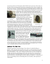
total of 1.5 degrees. After checking the pallets, I found that the lift faces were rather well
angled. I carefully filed off the wear, making sure to keep the angles as they were, then
polished the faces using a buff stick and white rouge on the “buffer polisher” machine.
Once the minimal wear was disposed of and the pallets were nice and shiny, I also filed
off some of the burrs created by the punch marks on the exit pallet arm. It looks better,
but to fully remove the punch marks would be to recreate the pallets, which is extremely
difficult. Finally, I put the escape pallets back into the clock and we checked the entrance
drop, which is always adjusted before the exit drop. We found
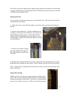
the entrance drop to be too large (due to the fact that material
was removed in the polishing process), so we put the pallets in a
vice and heated them gently while squeezing, being careful not
to break them. This achieved the desired effect of decreasing
the entrance drop. Having done that, we next checked exit
drop, which is adjusted by changing the distance from the
pallets to the escape wheel instead of opening or closing the pallets themselves. After
both sides had equal drop and sufficient lock (to ensure the wheel didn’t slip past or hit
the lift face), it was time to adjust beat rate and time keeping!
Beat and Rate Adjustments – Nuts and Knobs
With the movement ticking, the time had come to check the performance of the clock.
First, however, I had to set it up properly on the movement stand and adjust it to keep
time. The first thing I adjusted was the beat, or the consistency of the “tick-tocks” with
the goal of making the time between the beats equal. In other words, I wanted the escape
teeth to lock at the same relative point on each side of pendulum’s
arc. To do this, I loosened the screw where the leader attaches to
the pallet arbor, which is the part of the clock that connects the
pendulum to the escape pallets, and rotated it slightly so that it
drove the escape pallets the same distance on each side of the
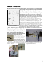
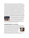
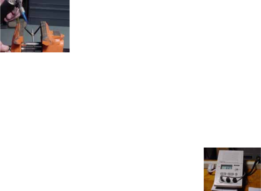
pendulum’s swing. To make sure the beat was correct, I used a
timing machine (also used to measure the rate). This machine
picks up the sound made by the clock and measures how much time passes between the
beats. Then it calculates the difference. After getting the beat nearly perfect,
Timing Machine