


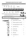
ASSEMBLY INSTRUCTIONS
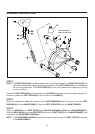
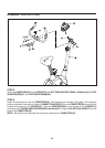
STEP 6
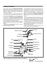
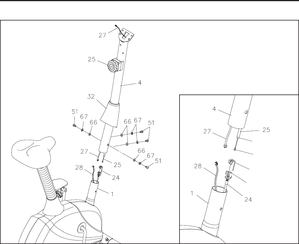
Slide the UPRIGHT SLEEVE(32) over the UPRIGHT(4). Set the TENSION KNOB(25) on the UPRIGHT(4)
at position "8", so the cable end extends out of the metal fitting as far as possible. Pull the ends of the
TENSION CABLE(24) and SENSOR WIRE(28) out of the MAIN FRAME(1). Refer to the inset drawing.
Connect the CABLE END of the TENSION KNOB(25) into the SPRING HOOK on the end of the TENSION
CABLE(24). Pull on the Cable of the TENSION KNOB(25) firmly so that enough cable is available to insert
the cable through the slot in the BRACKET. Then insert the METAL FITTING on the cable of the TENSION
KNOB(25) into the hole at the end of the slot in the BRACKET. Adjust the TENSION KNOB(25) and verify
that the SPRING HOOK moves when the TENSION KNOB(25) is adjusted.
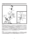
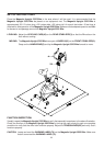
STEP 7
Connect the CONNECTION WIRE(27) to the SENSOR WIRE(28). Insert the UPRIGHT(4) onto the MAIN
FRAME(1) and secure with BUTTON HEAD BOLTS(M8x1.25x20mm)(51), LOCK WASHERS(M8)(67),
and ARC WASHERS(M8)(66). Slide down the UPRIGHT SLEEVE(32) to cover the bolt heads.
9
CABLE END
SPRING HOOK
BRACKET
METAL FITTING