


25
03/05 P/N 211014
H-18
H-15
P-1
P-20
P-19
P-17
P-11
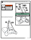
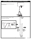
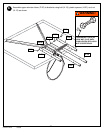
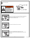
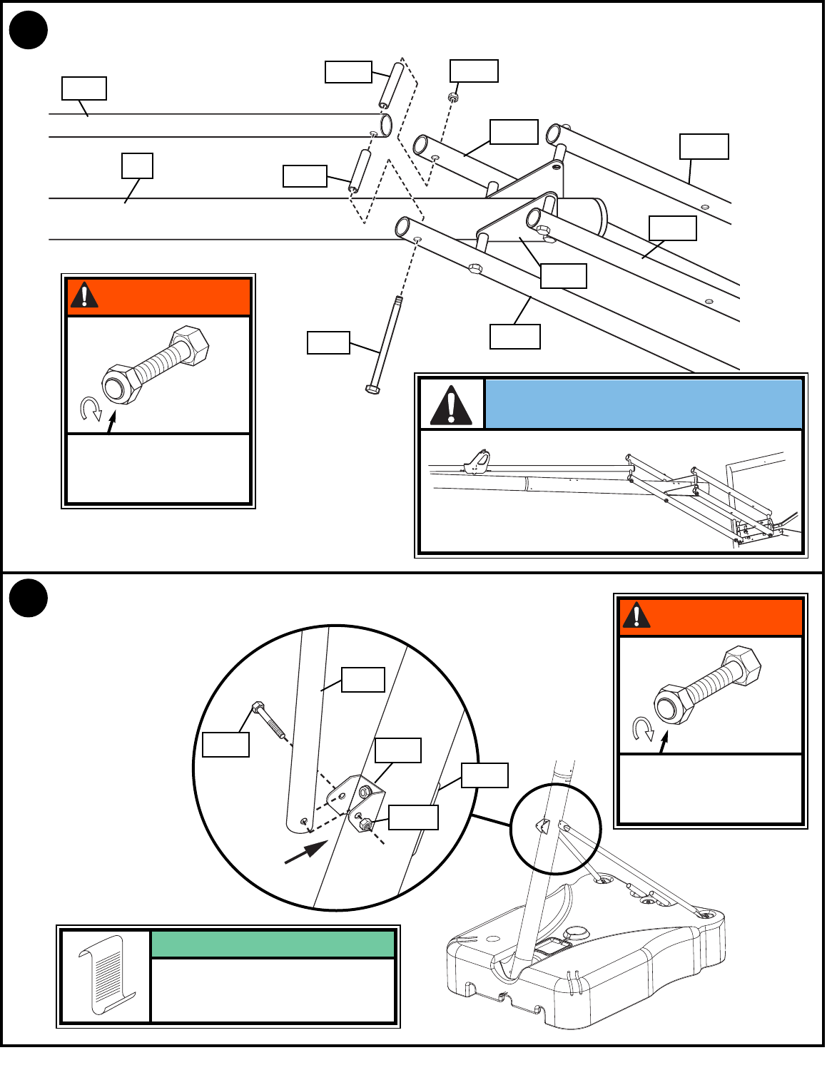
9.
Install handle assembly (P-10 and P-11) to lower elevator tubes (P-19) using bolt (H-18), spacers (H-14),
and nut (H-15) as shown.
P-20
P-19
H-14
H-14
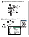
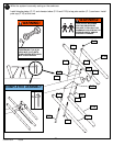
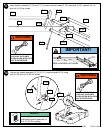
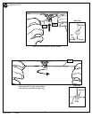
Secure the handle assembly (P-10 & P-11) to pole bracket (P-9) using
bolt (H-30) and nut (H-23) as shown.
10.
P-9
P-7
H-30
H-23
P-10
IMPORTANT!
Note orientation of handle.
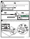
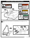
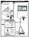
Before going on to next step, set
adjustable system assembly to
the 10’ (3.05 m) setting.
NOTE:
TIGHTEN BOLT (H-18) IN
LOCK NUT (H-15) UNTIL
FLUSH (EVEN) WITH LOCK
NUT’S OUTER EDGE.
WARNING!
TIGHTEN BOLT (H-30) IN
LOCK NUT (H-23) UNTIL
FLUSH (EVEN) WITH LOCK
NUT’S OUTER EDGE.
WARNING!