


11
03/05 P/N 211014
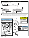
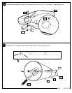
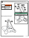
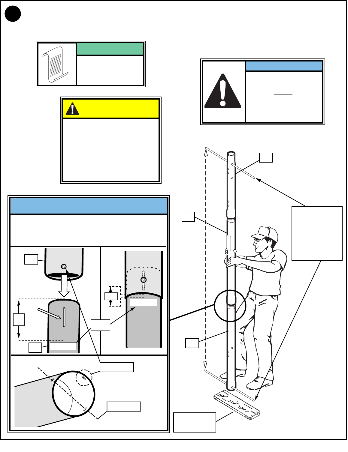
While maintaining alignment, bounce assembly and lower section (P-3) together as shown until they no
longer move toward taped reference mark.
P-1
P-2
P-3
3.
WOOD SCRAP
(NOT SUPPLIED)
TROUGH
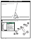
Align dimple of middle pole section (P-2)
into trough of bottom pole section (P-3)
as shown.
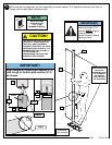
IMPORTANT!
POLE SECTIONS
SHOULD HAVE A
3-1/2" (9 CM)
MINIMUM OVERLAP.
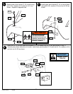
NOTE:
HOLE
DIMPLE
Bottom pole
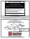
THE IDENTIFICATION STICKER IS
LOCATED 5" FROM THE END OF
THE POLE. WHEN PROPERLY
POUNDED TOGETHER, THE POLE
SECTIONS SHOULD HAVE A 3-1/2"
MINIMUM OVERLAP, LEAVING 1-
1/2" BETWEEN THE
OVERLAPPING POLE AND THE
IDENTIFICATION STICKER.
CAUTION!
5"
ID
STICKER
Bottom pole
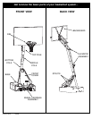
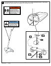
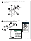
IMPORTANT!
Holes in top pole (P-1)
and bottom pole (P-3)
sections MUST
align to
correctly position
elevator system toward
playing surface.
RODS SHOWN ARE
FOR VISUAL
REPRESENTATION
OF ALIGNMENT
AND ARE NOT
SUPPLIED WITH
THE HARDWARE
P-2
P-3
1-1/2"