


13
“ASSEMBLY INSTRUCTIONS”
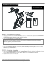
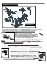
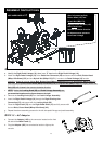
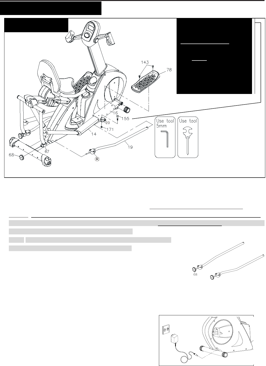
STEP 12 –
Pedal Linkage and Pedal Assembly
a. Identify the Right Pedal Linkage (19), there is an “R” decal on the Right Pedal Linkage (19).
b. Attach the Right Pedal Linkage (19) to the Pedal Arm Connector (20) and secure with one Bolt, Button Head
(M8xp1.25x40mm)(155) and one Nylock Nut (M8xp1.25)(171).
In order to let Pedal Linkage (19) function
smoothly, please do not over-tighten Bolt, Button Head (M8xp1.25x40mm)(155) and Nylock Nut (M8xp1.25)(171).
After fully securing Bolt, Button Head (M8xp1.25x40mm)(155) and Nylock Nut (M8xp1.25)(171), slightly loosen the
Bolt (155) with ¼ turn in the counter-clockwise direction.
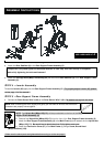
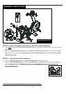
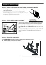
c. NOTE: Notice that Locking Knob (68) and Pedal Linkage Assembly are
pre-assembled together as the figure shows on the right.
d. Remove the Locking Knob (68) from the Pedal Linkage Assembly.
e. Insert the Right Pedal Linkage (19) through the Right Pivoting Arm
Connection (67) and secure with the Locking Knob (68).
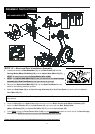
f. Place the Right Pedal (78) onto the Right Pedal Slider (16) and fully secure with
the two Bolts, Round Head (M8xp1.25x16mm)(143).
g. Repeat the above assembly process for the left side pedal linkage and pedal assembly.
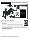
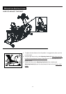
STEP 13 –
AC Adaptor
a. Connect the Adaptor (185) to the connector located on the front
left side of the Main Frame (1).
b. Plug the Adaptor (185) into an electrical outlet to light up the
console.
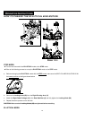
USE HARDWARE KIT
C
After fully securing Bolt,
Button Head (155) and
Nylock Nut (M8)(171),
slightly loosen the Bolt (155)
with ¼ turn in the
counter-clockwise direction
to release excess pressure
from Pedal Linkage