


8
45
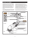
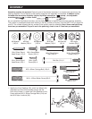
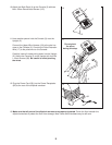
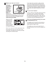
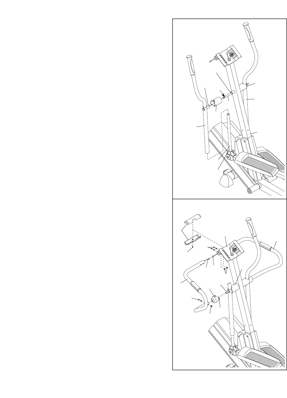
Lubricate
8. Apply a small amount of the included Teflon
®
lubricant
to a paper towel. Rub a thin film of the lubricant onto
each Chrome
Tube (45).
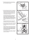
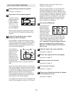
Identify the Left Upper Body
Arm (9), which is marked
with an “L.” Slide the Left Upper Body Arm onto the left
Chrome Tube (45). Slide the Right Upper Body Arm
(10) onto the right Chrome Tube (not shown). Make
sure that the Upper Body Arms are on the correct
sides. Next, slide an Upper Body Cover (15) onto the
post on each Upper Body Arm.
Apply grease to the Pivot Axle (16). Insert the Pivot
Axle into the Upright (2), the right Upper Body Cover
(15), and the Right Upper Body Arm (10). Next, push
the Pivot Axle into the Upright
until the left end of the
Pivot Axle is flush with the left side of the Upright.
Then, raise the Left Upper Body Arm (9), and insert
the Pivot Axle into the left Upper Body Cover and the
Left Upper Body Arm. Center the Pivot Axle and rotate
it so the indicated hole is in the position shown.
8
Hole
Grease
Post
9
10
15
15
16
2
9
T
ab
116
8
15
7
11
17
12
1
17
91
16
91
2
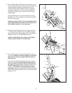
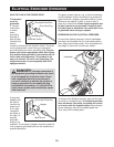
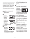
9. Have another person hold the Left Handlebar (7) near
the Upright (2) as shown. Connect the left Pulse
Sensor Wire (11) to the Pulse Extension Wire (17).
Slide a Handlebar Cap (12) onto the lower end of the
Left Handlebar.
Slide the upper end of the Left Handlebar (7) into the
tube on the front of the Upright (2), while sliding the
lower end of the Left Handlebar onto the Pivot Axle
(16). Attach the upper end of the Left Handlebar with
two M8 x 42mm Button Bolts (116) and two M8 Jam
Nuts (91); be careful not to damage the W
ires (1
1,
17) as you insert the Button Bolts. Make sure that
the Jam Nuts are resting in the hexagonal holes in
the tube on the front of the Upright.
Attach the lower
end of the Left Handlebar with an M8 x 35mm Button
Bolt (117) and an M8 Jam Nut (91). Press the tabs on
the Handlebar Cap (12) into the left Upper Body Cover
(15).
Attach the Right Handlebar (8) to the Upright (2) in the
same way.
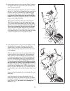
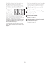
Hold the halves of the Upper Handlebar Cover (5)
around the tube on the front of the Upright (2).
Attach
the Upper Handlebar Cover with an M4 x 16mm Round
Head Screw (125);
be careful not to damage the
Wires (11, 17).
5
125