


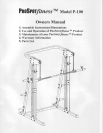
lnstructions
for Assembly
of the
PROSPOTy'tnessrM P-100
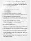
Before assembly,
choose a safe
location for
your
PROSPOffttuessrM P-100.
The PROSPOTlrzessrM P-100
has a
footprint of approximately 6'x
6'. The barbell
is
approximately
7' long. Locate
your
PROSPOTltrressrM
P-100
away from any source
of water.
Do not allow any
liquid
lo be
near
the
machine
or
spilled on
any
electrical
part.
Do not insert any object
into the electrical
box.
Approximate assembly
time
is
1/2 hours.
A flat area of 8' x 8' will be
required to assemble and
properly
use the PROSPOTIT/gssIM P-100.
You will need the following
tools and a helper to complete
the assembly:
.
5 mm
Allen Wrench
r
14 mm Box End Wrench
o
17 mm Box
End Wrench
.
19 mm Box End Wrench
Floor Padding, such as cardboard, to avoid scratching
your
floor during assembly.
A
good
pair
of scissors will be helpful
jn
separating
the
parts
from one
another
while removing
them from the
cartons.
HAND TIGHTEN all bolts.
DO
NOT fully tighten
bolts until instructed to
do
so.
Before assembly, separate
and identify the rightsided
parts
from
the left-sided
parts.
These
parts
are
easily
distinguished by the manner
in which
the
pre-drilled
holes align with corresponding
parts,
or are
identified
by
"L"&"R"stickers.
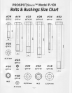
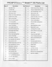
The PROSPOTlrressrM P-100 uses several different lengths of bolts. Be careful to use the correct length of
bolt called
for
at each step of assembly.
Refer to the sizing charts
provided.
.
WARNfNG: Never
perform
any maintenance on the PROSPOTfitnessrM
P-
100 while the Power Supply is
plugged
into the wall !!!
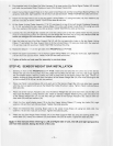
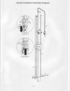
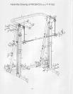
STEP # 1: MAIN FRAME ASSEMBLY
1. Place
the two
Base
Rails
(1
&
2)
opposite
each other in the center
of the assembly area as shown in
the
lllustration. Place
the
Lower Cross Brace
(3)
between the two Base Rails
(1
& 2) so that the side
pre-drilled
holes
of
the Base Rails
('1,
2) align with the end holes of the Lower
Cross
Brace
(3).
Carefully thread the Base Rail Wire Harness
(8)
through the corresponding big
end
holes
of the
Lower
Cross
Brace
(3)
then
pull
the Wire Harness
(8)
out of the back big holes of the Lower Cross Brace
(3).
Attach the two Base Rails
(1
& 2) to the Lower Cross Brace
(3)
using
two Cross
Brace Backing
Plates
(13),
four bolts
(28),
eight washers
(18)
and four nuts
(20)
as shown. HAND TIGHTEN the
bolts at this time.
Attach the Right
Upright
Guidepost Assembly
(7,
10, 53) and the
two Upright Support Plates
(6)
to the Right
Base Rail
(1)
using four bolts
(28),
eight
washers
(18)
and
four
nuts
(20)
as shown. HAND TIGHTEN
the
bolts at this time.
(Note:
The long end of the Upright Support Plate
(6)
should
point
to
the rear
of the
machine
as shown in the
illustration).
Attach the Left Upright Guidepost Assembly
(9,
12, 53) and the two Upright
Support
Plates
(6)
to the Left
Base
Rail
(2)
using
four
bolts
(28),
eight
washers
(18)
and four nuts
(20)
as shown. HAND TIGHTEN the
bolts at
this time.
(Note:
The long end of the Upright Support Plate
(6)
should
point
to the rear of the
machine as shown in the illustrationl.
2.
3.
5.
I