


6
ASSEMBLY
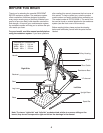
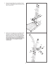
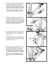
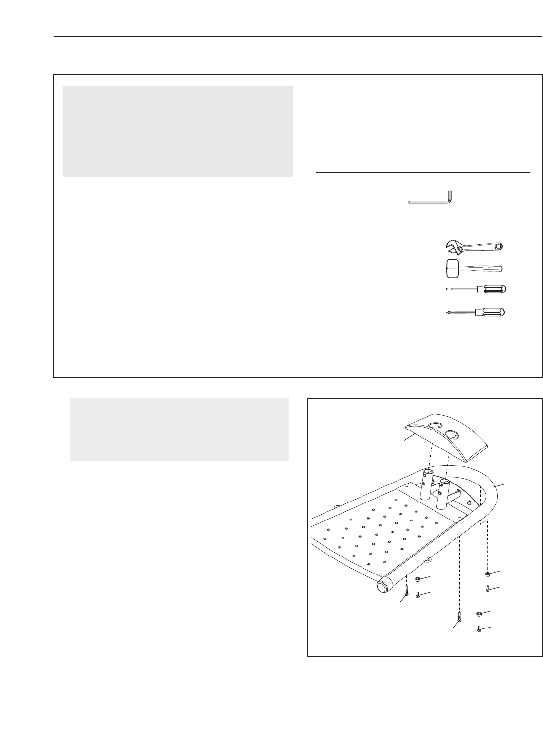
1.
Attach three Plastic Feet (1) to the Base (2) with
three M4 x 16mm Screws (61).
Attach the Base Cover (4) to the Base (2) with
two M4 x 50mm Screws (66).
1
Before beginning assembly, make sure that
you understand the information in the box
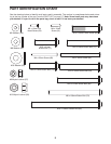
above. To identify small parts, use the
PART IDENTIFICATION CHART on page 5.
4
2
1
61
1
61
1
61
66
66
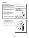
Before beginning assembly, carefully read the
following information and instructions:
•
Assembly requires two persons.
• Because of its weight and size, the resistance
system should be assembled in the location
where it will be used. Make sure that there is
enough clearance to walk around the resistance
system as you assemble it.
• Place all parts in a cleared area and remove the
packing materials. Do not dispose of the packing
materials until assembly is completed.
• T
ighten all parts as you assemble them, unless
instructed to do otherwise.
• As you assemble the resistance system, make
sure all parts are oriented as shown in the draw-
ings.
• For help identifying small parts, use the PART
IDENTIFICATION CHART.
The included hex key and grease, and
the following tools (not included) may be
required for assembly:
• Two adjustable wrenches
• One rubber mallet
• One standard screwdriver
• One Phillips screwdriver
Assembly will be more convenient if you have a
socket set, a set of open-end or closed-end
wrenches, or a set of ratchet wrenches.
Make Assembly Easier
Everything in this manual is designed to ensure
that the resistance system can be assembled
successfully by almost anyone. Most people find
that by setting aside plenty of time, assembly will
go smoothly.