


11
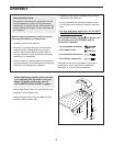
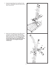
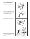
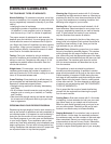
14. Note: This step may be easier if the resistance
system is tipped over forward.
Wrap the wire found inside the Rear Frame (10)
a
round the end of the Long Cable (42). Pull the
Long Cable through the Rear Frame and out of
the Swivel Arm (12).
Have a second person
hold the cable end until step 15 is completed.
Discard the wire.
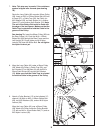
Hold a 90mm Pulley (38) next to the Long Cable
(42) as shown. Insert an M10 x 132mm Button
Bolt (69) into a Guard (37), a Cable Trap (39), the
Pulley, an M10 Washer (59), an 8mm Spacer
(41), another Guard (37), and another 8mm
Spacer (41).
Note: The end of the Button Bolt
must be flush with the edge of the last Spacer.
Make sure that the Cable Trap is oriented to
hold the Cable in the groove of the Pulley. The
flat edge of each Guard must be toward the
Rear Frame (10).
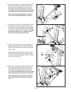
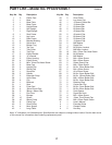
See the inset drawing
. Insert the 90mm Pulley
(38) into the Rear Frame (10). Push the M10 x
132mm Button Bolt (69) through the Rear Frame
and the Right Upright (7). Tighten an M10 Nylon
Locknut (56) onto the Button Bolt.
Tighten the M10 Nylon Locknuts (56) used in
steps 3 and 7.
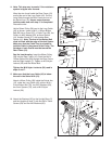
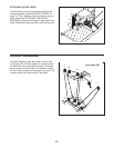
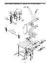
15. Make sure that the Long Cable (42) is below
the rod in the Swivel Arm (12).
Attach a 90mm Pulley (38) inside the Swivel Arm
(12), under the Long Cable (42), with an M10 x
51mm Button Bolt (74), two M10 Washers (59),
two 5mm Spacers (76), and an M10 Nylon
Locknut (56).
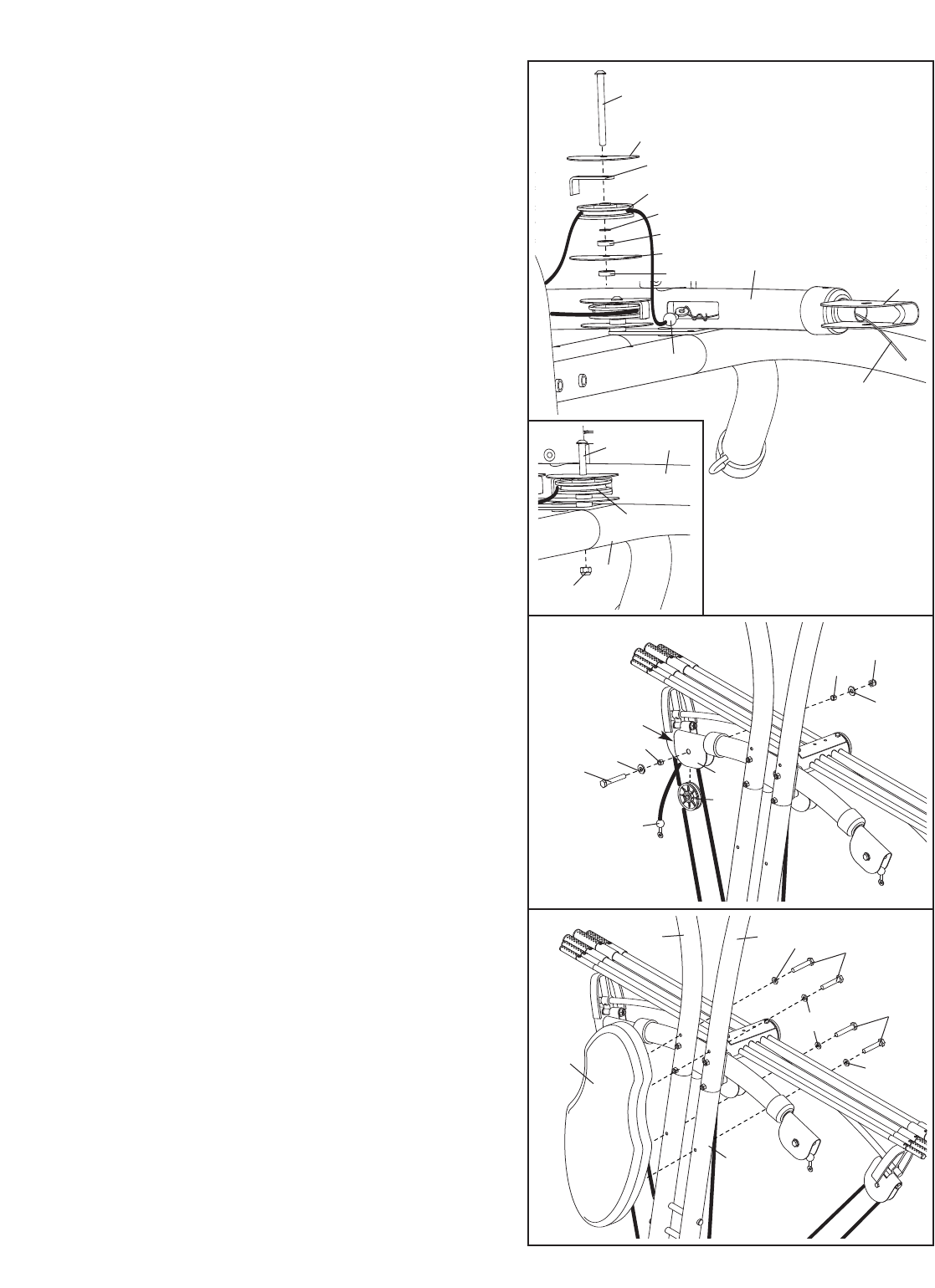
16. Attach the Backrest (30) to the Upright Base (5)
and the Uprights (6 and 7) with four M6 x 76mm
Screws (64) and four M6 Washers (60).
74
42
12
38
59
59
56
Rod
15
16
76
76
30
5
6
60
60
60
7
64
64
14
69
37
39
38
41
41
37
59
56
69
38
42
12
10
Wire
10
7