


7
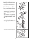
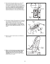
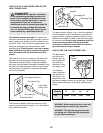
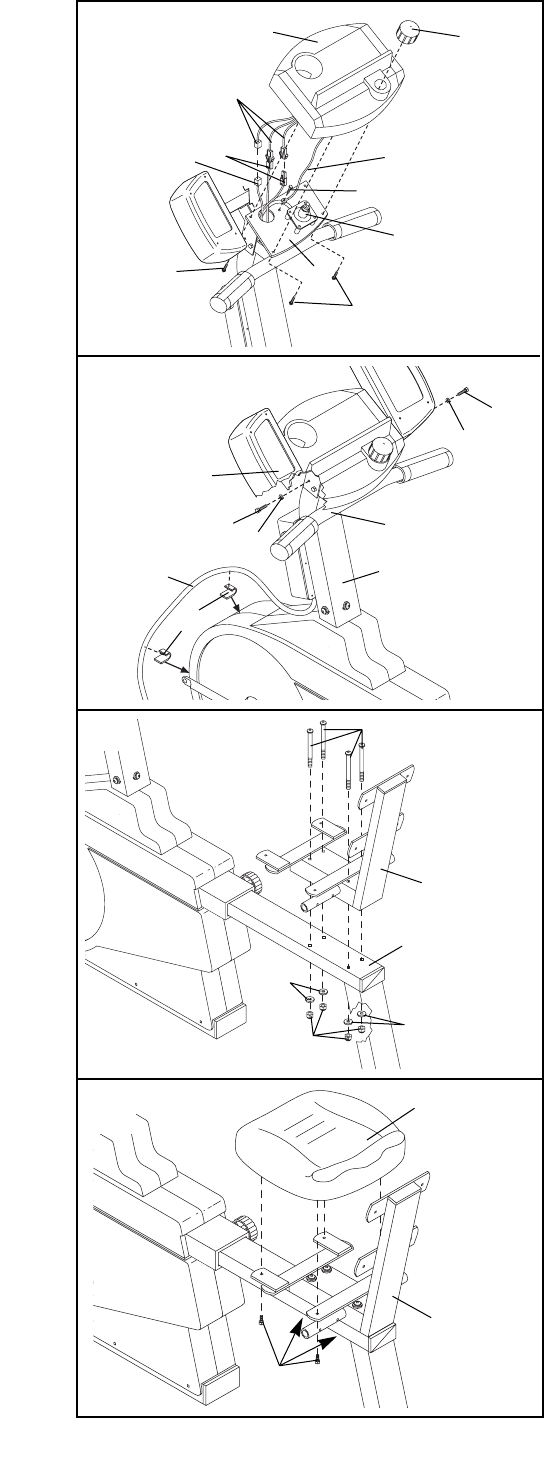
6. Finish attaching the Handlebar (4) and the Light
Frame (82) to the Upright (2) with two more M6 x
25mm Hex Head Screws (14) and two more M6
Split Washers (67). Tighten all four Hex Head
Screws.
Remove the backing from the Cord Clips (95) and
and press them onto the exercise cycle in the indi-
cated locations. Insert the Power Cord (73) into the
Cord Clips. Make sure that the Power Cord can-
not get caught on the pedals while you are exer-
cising.
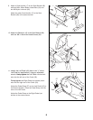
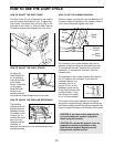
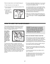
7. Attach the Seat Bracket (69) to the Seat Frame (3)
with four M10 x 105mm Button Head Bolts (70), four
M10 Flat Washers (71), and four M10 Nylon
Locknuts (72).
8. Attach the Seat (16) to the Seat Bracket (69) with
four M6 x 16mm Hex Head Screws (24).
71
71
69
69
3
72
70
24
16
14
14
2
4
6
7
8
67
67
95
73
82
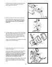
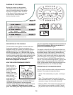
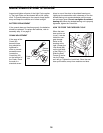
5. Connect the Reed Switch Wire (13) and the two
Extension Wires (41) to the corresponding wires on
the Console (8).
If your Console (8) has a ground wire, attach it to
the Upright (2) with an M4 x 16mm Screw (34).
Next, attach the Console (8) to the Upright (2) with
four #8 x 5/8Ó Screws (22).
Press the Resistance Knob (9) onto the Resistance
Control (10). Be sure that the mark on the Knob is
correctly aligned.
Console
Wires
Ground
Wire
10
8
9
13
34
2
41
22
22
5