


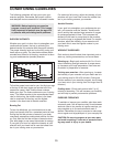
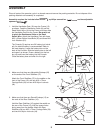
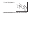

Place all parts of the exercise cycle in a cleared area and remove the packing materials. Do not dispose of the
packing materials until assembly is completed.
Assembly requires the included allen wrench , a phillips screwdriver and two adjustable
spanners .
5
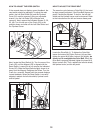
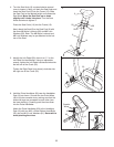
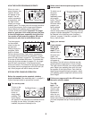
2. Make sure that there are Adjustable Endcaps (25)
on the ends of the Front Stabiliser (27).
Attach the Front Stabiliser (27) to the saddle on the
front of the Frame (13) with two M10 x 75mm
Carriage Bolts (54) and two M10 Nylon Locknuts
(44).
3. Make sure that there are Round Endcaps (15) on
the ends of the Rear Stabiliser (16).
Hold the Rear Stabiliser (16) against the saddle on
the rear of the Frame (13), with the square holes
facing away from the saddle. Attach the Rear
Stabiliser with two M10 x 75mm Carriage Bolts (54)
and two M10 Nylon Locknuts (44).
ASSEMBLY
56
27
25
25
44
13
13
54
54
44
15
16
Square
Holes
15
3
2
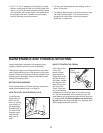
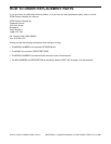
1. Hold the Handlebar Post (19) near the Frame (13)
as shown. Feed the Resistance Cable (6) and the
Reed Switch Wire (4) into the Frame, and then slide
the Handlebar Post into the Frame. Be careful not
to pinch the Resistance Cable or the Reed
Switch Wire. Attach the Handlebar Post with three
M10 x 22mm Button Head Bolts (55) and three M10
Lock Washers (61).
The Console (5) requires one 9V battery (not includ-
ed). An alkaline battery is recommended. Refer to
the inset drawing. Locate the battery door on the
back of the Console. Slide the battery door to the left
and open it as shown. Press a battery into the bat-
tery clip and insert the battery into the Console.
Close the battery door and slide it to the right.
61
61
55
55
55
5
13
4
6
19
5
Battery
Battery
Clip
Battery
Door
1