


6
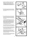
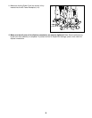
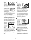
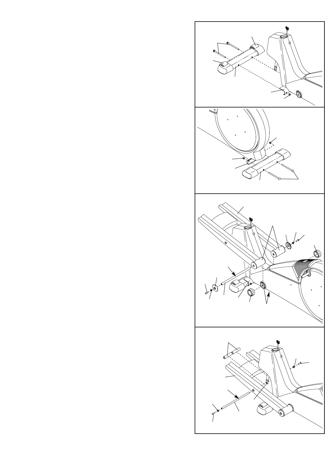
2. While another person lifts the back of the Frame (1),
attach the Rear Stabilizer (4) to the Frame with two
M10 x 112mm Carriage Bolts (34) and two M10 Nylon
Locknuts (106).
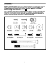
34
4
1
3
59
108
18
45
102
104
Grease
Tubes
103
108
45
102
18
1
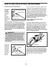
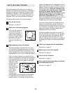
3. Slide an M8.5 Washer (45) and a Ramp Cap (102)
onto an M8 x 19mm Patch Screw (108). Tighten the
Patch Screw into one end of the Frame Axle (104).
Next, apply a small amount of the included grease to
the Frame Axle.
Locate the two Frame Bushings (103) in the Frame
(1). Press a Ramp Shield (18) onto each Frame
Bushing. Next, align the indicated tubes on the Ramp
(59) with the Ramp Shields. Make sure that the
Ramp is turned as shown. Insert the Frame Axle
(104) into the Ramp, the Ramp Shields, and the
Frame Bushings. Note: It may be helpful to use a rub-
ber mallet to insert the Frame Axle.
Slide an M8.5 Washer (45) and a Ramp Cap (102)
onto an M8 x 19mm Patch Screw (108). Tighten the
Patch Screw into the other end of the Frame Axle (104).
2
106
106
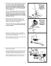
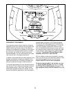
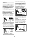
4. Slide an M6 Large Washer (94) onto an M6 x 16mm
Button Screw (109). Tighten the Button Screw into one
end of the Incline Axle (100). Next, apply a small
amount of grease to the Incline Axle.
Raise the Ramp (59). Insert the Incline Axle (100)
through one side of the Ramp, through a Ramp
Spacer (99), through the end of the Incline Motor (82),
through another Ramp Spacer (99), and then through
the other side of the Ramp.
Slide an M6 Large Washer (94) onto an M6 x 16mm
Button Screw (109). Tighten the Button Screw into the
other end of the Incline Axle (100).
99
59
94
109
100
82
94
109
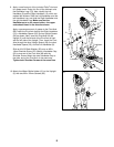
4
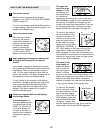
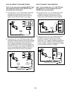
1. Identify the Front Stabilizer (3). While another person
lifts the front of the Frame (1), attach the Front
Stabilizer to the Frame with two M10 x 112mm
Carriage Bolts (34) and two M10 Nylon Locknuts
(106). Make sure that the Front Stabilizer is turned
so the Wheels (32) are not touching the floor.
3
106
32
32
34
1
1
Grease