


8
8
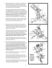
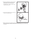
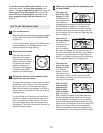
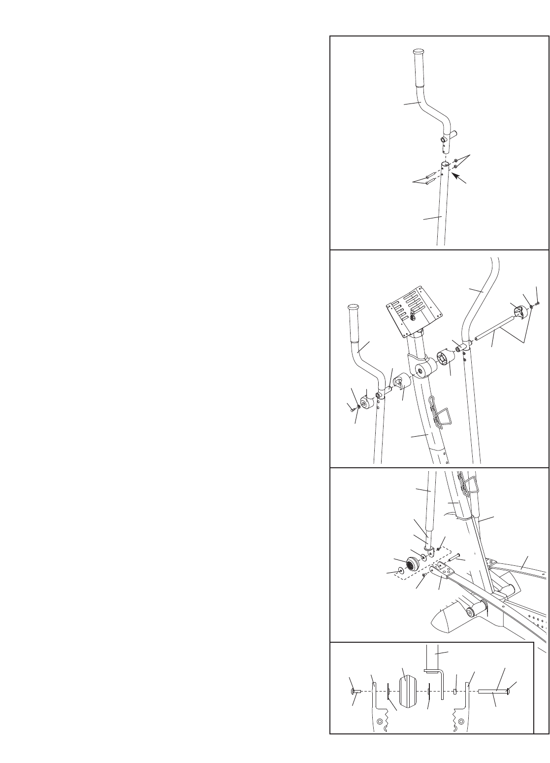
8. Apply a generous amount of grease to the Pivot Axle
(108) and to the two M8.5 Small Washers (53). Insert
the Pivot Axle into the Upright (2) and center it. Reapply
grease to both sides of the Pivot Axle.
Identify the Left and Right Handlebars (9, 10), which
are marked with stickers. Slide a Handlebar Spacer
(25) onto the short tube on each Handlebar, and slide
the Handlebars onto the Pivot Axle (108).
Make sure
that the Handlebars are on the correct sides.
Orient the two Handlebar Caps (23) as shown, and
press the small tabs on the Handlebar Caps into the
two Handlebar Spacers (25). Tighten an M8 x 19mm
Shoulder Screw (22) with an M8.5 Small Washer (53)
into each end of the Pivot Axle (108).
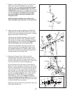
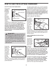
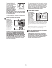
9. Remove the Chrome Tube (118) from the left
Handlebar Leg (79).
Apply a small amount of the
included
T
eflon
®
lubricant to a paper towel, and rub a
thin film of lubricant onto the Chrome Tube. Then, rein-
sert the Chrome Tube into the Handlebar Leg.
See the drawing at the right and the inset drawing.
Apply a thin film of grease to the shaft of a Union Bolt
Set (27). Insert the shaft of the Union Bolt Set into the
side of the left Flex Bar (14) closest to the Upright (2),
and then slide a 4.7mm Spacer (143) onto the shaft.
Next, slide the end of the left Chrome Tube (118) onto
the shaft and
onto the Spacer. Then, slide a Wheel
Bushing (28), a Ramp Wheel (119), and another
Wheel Bushing onto the shaft. Make sure that all
parts are oriented exactly as shown.
Insert the shaft
completely through the Flex Bar and tighten the screw
of the Union Bolt Set into the shaft.
Repeat this step to attach the right Chrome Tube (118)
to the right Flex Bar (14).
9
9
22
22
53
53
23
23
25
10
2
2
108
Grease
Grease
Lubricate
25
Tube
Tube
79
27
118
143
119
118
27
28
28
27
Grease
Shaft
Screw
14
143
28
28
1
18
119
14
27
14
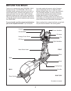
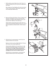
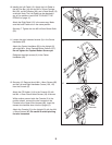
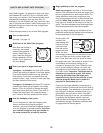
7. Identify the Left Handlebar (9), which is marked with a
sticker. Insert the Left Handlebar into one of the
Handlebar Legs (79);
make sure that the Handlebar
Leg is turned so the hexagonal holes are on the
indicated side.
Attach the Left Handlebar with two M8
x 43mm Button Bolts (50) and two M8 Nylon Locknuts
(46).
Do not tighten the Button Bolts yet. Make
sure that the Nylon Locknuts are seated in the
hexagonal holes.
Attach the Right Handlebar (not shown) to the
other Handlebar Leg (not shown) in the same way.
7
9
79
Hexagonal
Holes
50
46
14