


5
ASSEMBLY
Assembly requires two people. Set the treadmill in a cleared area and remove the packing materials. Do not
dispose of the packing materials until assembly is completed.
Assembly requires a phillips screwdriver (not included).
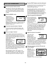
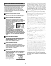
2. Slide the Left and Right Base Mounts (104, 78) onto
the plastic pins on the sides of the Console Base (91).
Next, carefully insert the Left and Right Base Mounts
(104, 78) into the Upright (71) as shown.
Refer to the inset drawing. Carefully feed all wires into
the hole in the Upright (71) as shown. Make sure that
the wires are routed through the notch in the base
mount and under the plastic pin. Be careful not to pull
on the wires or they may become disconnected
from the console.
78
91
71
104
2
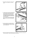
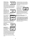
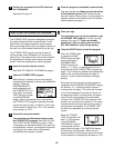
3. Slide the Left and Right Lower Base Mounts (105, 79)
onto the Left and Right Base Mounts (104, 78). Attach
the Lower Base Mounts with eight 3/4” Screws (77) as
shown. Be careful not to overtighten the Screws.
77
105
104
78
79
77
3
Notch
Pin
71
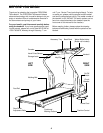
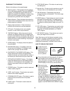
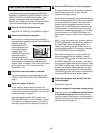
1. Note: One person must hold the Console Base (91)
near the Upright (71) during steps 1, 2, and 3. If this
is not done, the wire harness connecting the con-
sole to the treadmill may be permanently damaged.
Hold the Console Base (91) near the Upright (71).
Refer to inset drawing A. Connect the Wire Harness
(85) to the Console Wire Harness (121). Connect the
4” Ground Wire (120), the 54” Hand Pulse Wire (95)
and the 25” Hand Pulse Wire (83) to the Pulse Wire
Harness (77) (make sure that the Wires with tags are
connected to each other).
91
1
71
A
85
95
83
120
121
77