


12
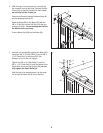
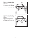
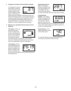
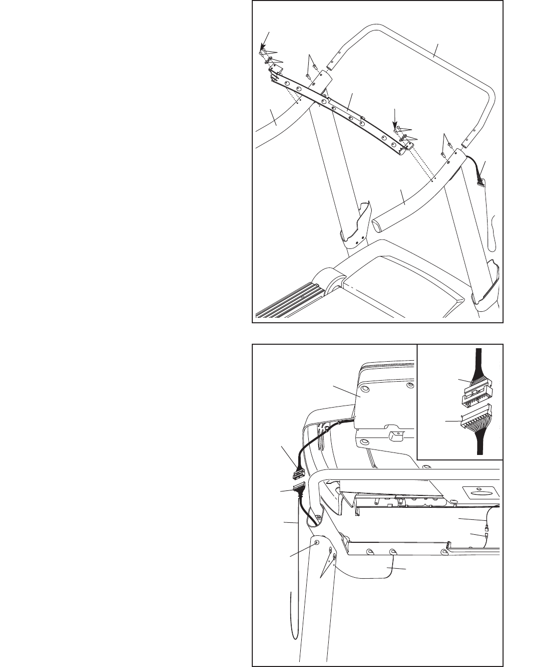
13. Firmly tighten two 5/16" x 1" Patch Bolts (4) and
the four 5/16" x 1" Flat Head Patch Bolts (14)
(only one side is shown).
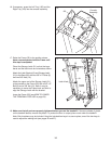
With the help of a second person, hold the con-
sole assembly near the Right Handrail (83) and
the Left Handrail (not shown).
Connect the Upright Wire (87) to the console
wire. See the inset drawing. The connectors
should slide together easily and snap into
place. If they do not, turn one connector and try
again. IF YOU DO NOT CONNECT THE CON-
NECTORS PROPERLY, THE CONSOLE MAY
BECOME DAMAGED WHEN YOU TURN ON
THE POWER. Remove the wire tie from the
Upright Wire.
Connect the ground wire from the console as-
sembly to the Console Ground Wire (52).
Console
Assembly
13
Console
Wire
Wire
Tie
Ground Wire
83
87
4
52
87
Console
Wire
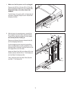
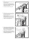
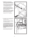
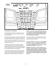
12. IMPORTANT: To avoid damaging the
Crossbar (107), do not use power tools and
do not overtighten the #10 x 3/4" Screws (2).
O
rient the Crossbar (107) as shown. Attach the
Crossbar to the Handrails (82, 83) with four #10
x 3/4" Screws (2) and four #10 Star Washers
(12); do not tighten the Screws yet.
Insert the Console Frame (102) into the
Handrails (82, 83). Attach the Console Frame
with four 1/4" x 1" Patch Bolts (9); do not
tighten the Patch Bolts yet. Be careful not to
pinch the Upright Wire (87).
Tighten one #10 x 3/4" Screw (2) in each end
of the Crossbar (107); do not overtighten the
Screws. Then, tighten the other #10 x 3/4"
Screw (2) in each end of the Crossbar.
Tighten the four 1/4" x 1" Patch Bolts (9).
12
107
12
9
2
83
102
8
2
87
9
12
2
F
irst
First
14