


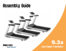


9.3x Low-Impact Treadmills Assembly Guide 4
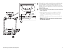
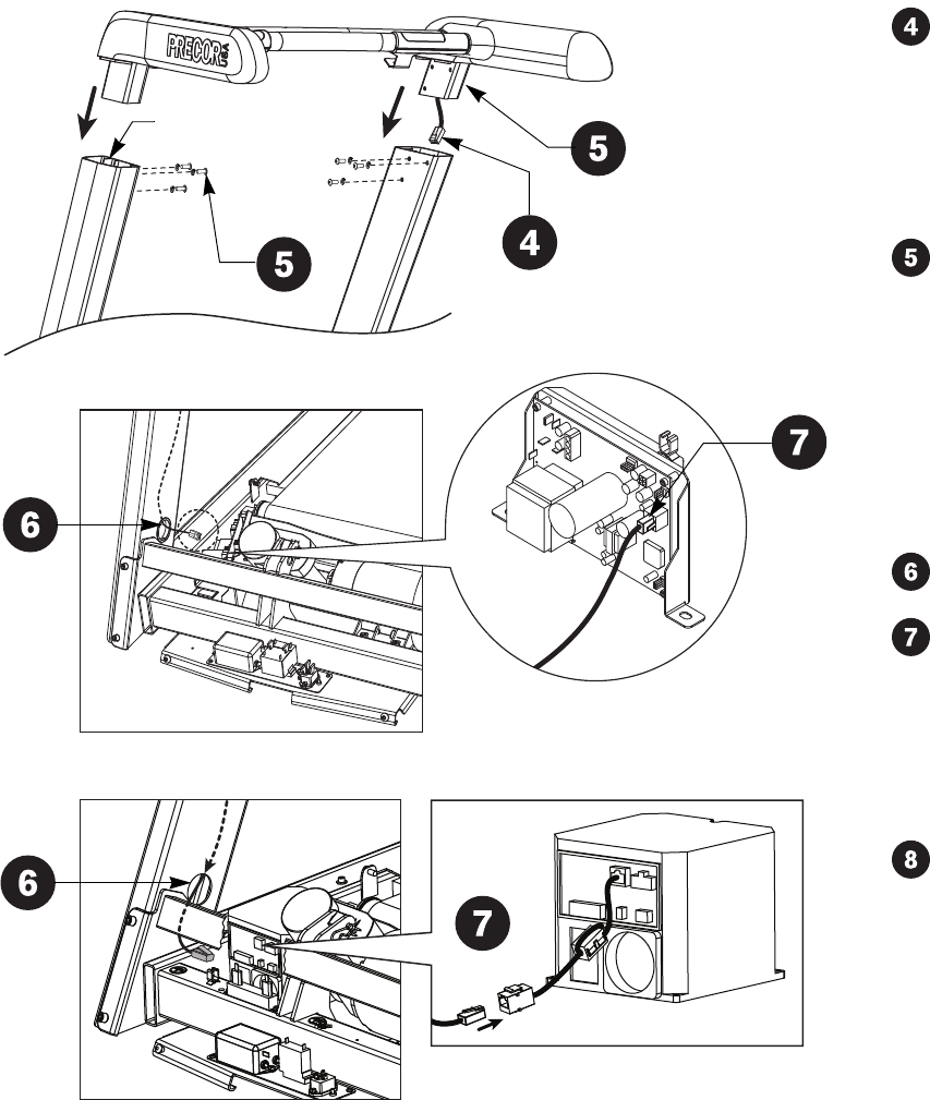
Unwrap the cable and remove the kinks. Ask your assistant to hold
the handrail extensions while you feed the cable inside the right
upright support. Make sure the cable connector rests on the floor at
the base of the upright support.
CAUTION: Be aware of the handrail extensions when you are
working around the front of the unit. It is easy to bump your
head or sustain other injuries if you ignore the location of the
handrail extensions.
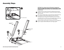
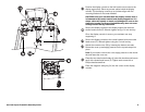
Have your assistant hold the handrail assembly above the upright
supports. Tip the assembly forward so the mounting brackets slide
along the interior rails inside the upright supports. Align the
mounting holes and insert six buttonhead screws (B) and six split
washers (D). For easier assembly, insert the top rear fasteners first.
Then, lift the handrail extensions and insert the bottom front
fasteners. Align the top front mounting holes and thread the two
remaining fasteners. Finger tighten.
Important: Make sure the fasteners do not pinch the cable. Cables
damaged by improper installation will not be covered by the Precor
Limited Warranty.
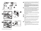
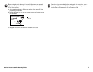
Pull the cable connector through the hole in the right upright
support.
For 120 V models, connect the display cable to its receptacle on the
electronics board. The tab on the cable connector faces the front of
the treadmill. An audible click is heard when the cable is properly
attached.
For 240 V models, connect the display cable to the jumper cable.
An audible click is heard when the cable is properly attached.
Note: Place the excess cable inside the upright support.
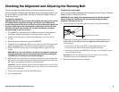
Tighten all mounting screws.
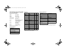
a. Start at the base and use the ¼-inch hex key to alternately tighten
the eight fasteners that secure the upright supports to the base
assembly. Refer to steps 2 and 3.
b. Use the ³⁄₁₆-inch hex key to wrench tighten the six screws that
secure the handrail extensions to the upright supports. Refer to
step 5.
Interior rail
120 V
240 V