


PBFS01 EXS00 BASE U-NIT ASSEMBLY INSTRUCTIONS (~,TEP #2)
24.
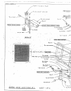
Attach eight (8) PARAGLIDE STRIPS to the ADJUSTABLE SEAT FRAME and the :BASE SEAT
SUPPORT as shown in DETAIL A and B on the reverse side of the main assembly drawing for STEP
#2, (SHEET #3 of 6), using the following steps:
A.
Thoroughly clean all inside and outside surfaces where the paraglide strips sre ::o be attached.
25.
B.
Remove the paper backing fi-om the paraglide strips and finnly apply them to alI of the shown
surfaces (8 Places).
.-
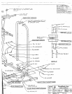
Attach the SEAT PAD to the ADJUSTABLE SEAT FRAME, using two (2) 3/8 x 3 BOLTS, two (2)
LOCII WASHERS, and two (2) 3/8 WASHERS. BE SURE TO POSITION THE PA]) SO TI-t~T TI-IE
METAL, HIDEM WELT CLIP IS FACING LNTO TIlE MAIN BACK SUPPORT.
26. Place the ADJUSTABLE SEAT FRAME ASSEMBLY into the slide receptacle on the BASE SEAT
SUPPORT, disengaging the SPRING PIN ASSEMBLY until the plunger engages flue first adjustment
hole.
27.
Install one (1) thumbscrew into the BASE SEAT SUPPORT.
28.
Attach the PRESS ARM to the TOP BOOM SECTION, by sliding the PRESS ARM BEARING
SHAFT through the PRESS ARM and the TOP BOOM SECTION until it is flush with both sides.
Securely tighten two (2) 5/16 SET SCREWS (using a 5/32 inch hex key) through the collars on
PRESS ARM into the PRESS ARM SUPPORT SHAFT. NOTE: POSITION PRESS ARNI SO TI-I&T
T/:~ EX500 DECAL IS FACING OUT AWAY FItOM THE MACHINE.
29.
Install the two (2) 3/8 DIA. X 2 IN. BUSHING PULLEYS between the fiats on the PIq2ESS AP~M, using
two (2) 3/8 x 3 BOLTS, four (4) 3/8 WASHERS, two (2) 3/8 LOCK
30.
Attach two (2) 5 IN. GRIPS and two (2) 7 IN. GRIPS onto the straight and angled P]LE.~S
HANDLES, NOTE: If a lubricant is required, RUBBING ALCOHOL thoroughly coating the inside
" of the grip is the best material to use.