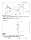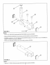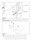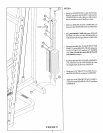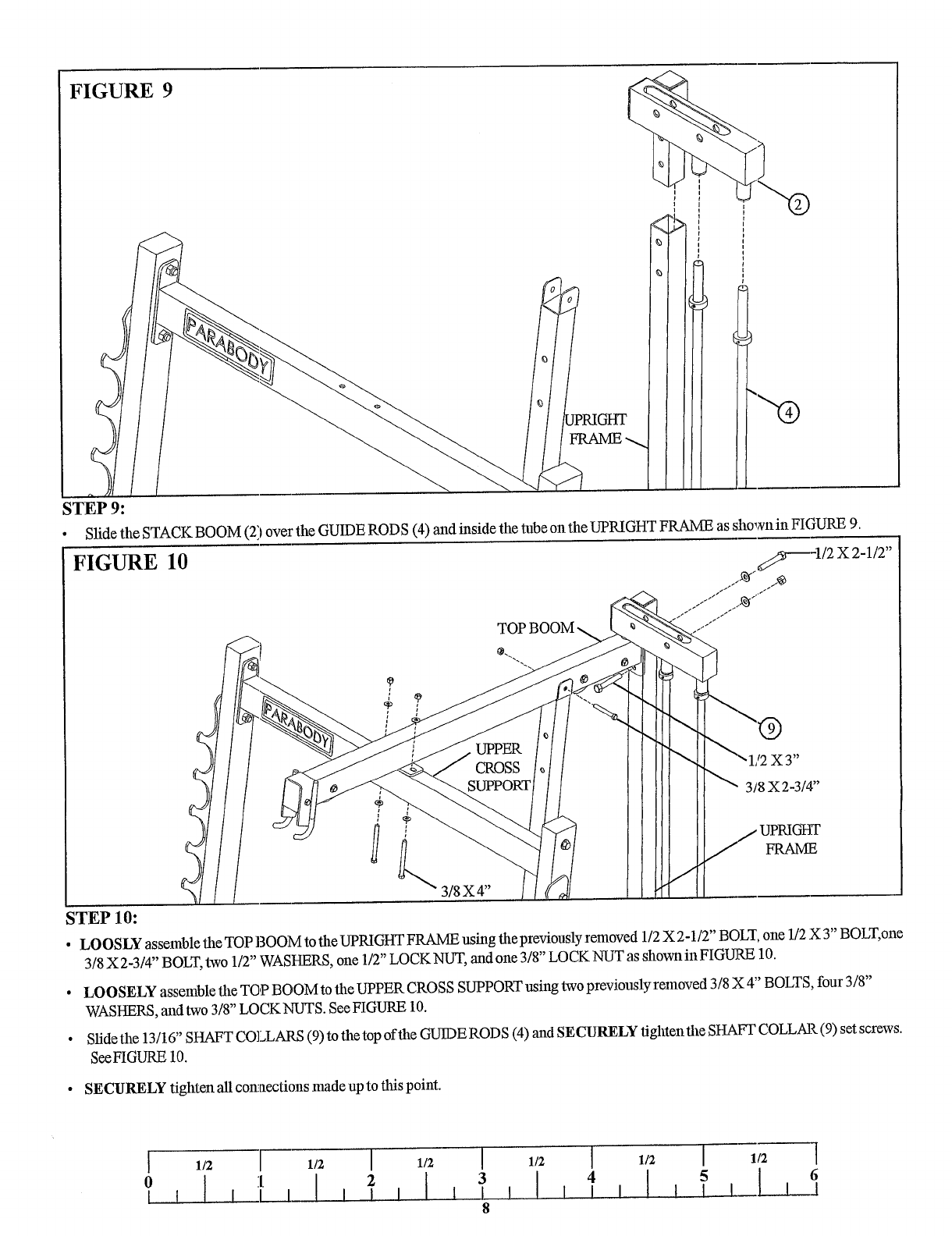
FIGURE 9
STEP 9:
~PRIGttT
Slide the STACK BOOM (21 over the GUIDE ROD S (4) and inside the tube on the UPRIGHT FRAME as shown in FIGURE
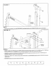
FIGURE 10
;TEP 10:
~¢~
-1/2 X 2-1/2"
"1/2 X 3"
¯ LOOSLY assemble the TOP BOOM to the UPRIGHT FRAME using the previously removed 1/2 X 2-1/2" BOLT, one 1/2 X 3" BOLT, oue
3/8 X 2-3/4" BOLT, two 1/2" WASHERS, one 1/2" LOCK NUT, and one 3/8" LOCK NUT as shown in FIGURE 10.
¯ LOOSELY assemble the T()P BOOM to the UPPER CROSS SUPPORT using two previously removed 3/8 X 4" BOLTS, four 3/8"
WASHERS, and two 3/8" LOCK NUTS. See FIGURE 10.
¯ Slide the 13/16" SHAFT COLLARS (9) to the top of the GUIDE RODS (4) and SECURELY tighten the SHAFT COLLAR (9) set screws.
See FIGURE 10.
¯ SECURELY tighten all COlmections made up to this point.
I 1/2
I 1/2 I
1/2
I
1/2
I
1/2
I
1/2
l
6
I t I I I I
8


