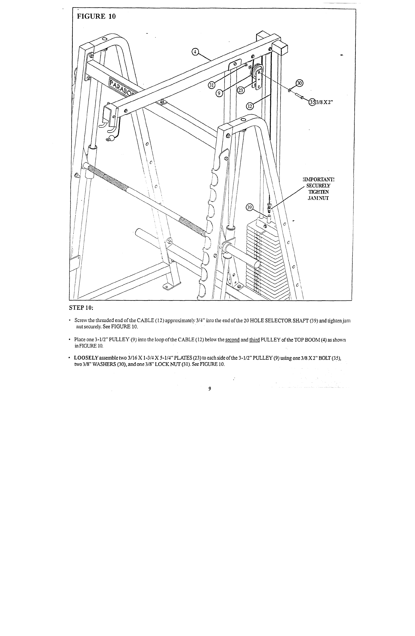
FIGURE 10
"(~3/8 X 2"
STEP 10:
¯ Screw the threaded end of the CABLE (12) appro~mately 3/4" into the end of the 20 HOLE SELECTOR SI-I.4k-T (39) and tighten
nut securely. See FIGURE 10.
¯
PlaCe one 3-1/2" PULLEY (9) into the loop of the CABLE (12) below the second and third PULLEY of the TOP BOOM (4) as
in HGURE 10.
¯
LOOSELY assemble two 3/16 X 1-3/4 X 5-1/4" PLATES (23) to each side of the 3-1/2" PULLEY (9) using one 3/8 X 2" BOLT (35),
two 3/8" WASHERS (30), and one 3/8" LOCK NUT (31). See FIGURE 10.


