


866101 ASSEMBLY INSTRUCTIONS
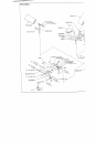
;\truth eight (8) PARAGLIDE STRIPS to tile WOLFF SLEEVE (FOUR ON EACH END) as shown
(DETAIL A) using the foliowin,,~ steps;
¯
Tllorou-hly clean all surf,aces ~vhere the PARAGLIDE STRIPS are to be attached.
¯
Renmve tile PARAGLIDE STRIPS from the paper backing and firmly, apply thenl to all shown
,~uri’accs.
’7. I) I.J-PIN throu,=,h the BUSHING of the WOLFF SLEEVE as shown on drawing, and attaci~
NUT to lhe end of the U-PIN.
.’-;l-’.(’I RELY AsSenlhle one (I) SPRING PIN ASSEMBLY to tile SPRING PIN BARREL,. ofthe
\V()LFF 5;LEEVE as shown in (DETAIL B). (!!! IMPORTANT !!! TIGHTEN THE NUT
.KPRING PIN ASSEMBLY SECURELY)
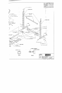
Pull ht~ck Ihe SPRING PIN on the WOLFF SLEEVE and slide it over the end of tile BENCH SLIDE as
shm~ n Oil. drawing. Engage the SPRING PIN into one of the adjustrnent holes. Secure the WOLFF
SLEEVE in place with one (I) "FHUMBSCREW.
I).
I.()().~ELY assemhle one I 1 ) ’FHUMBSCREW to the UPRIGHT TUBE of the BENCH FRAME
¯ .ht~wn oil dr;.r, ving. (THIS WILL BE USED TO SECURE ATTACHMENTS IN PLACEI~
..\uach ~mc (I) I-I/4 IN. SQ. Rt;BBER BUMPER to the SLIDE SUPPORT as shown Oil drawing.
.’,;E( I. REL~ assemble tile .SLIDE SUPPORT to the end of the BENCH SLIDE as shown cn drawilm
usin~ ~mc I I I 3 ,q X 2-3 4 IN. BOI.T. two (2) 3/8 IN WASHERS. and one ( I I 3.;8 IN. LOCK NUT.
.,Milch two (2) CARRIAGE G( IIDES to the top of the BENCH FRAME where tile SLil)E SUPPORT
makes conlact. ~e~ drawing.
Assemble the SEAT PAl) to the WOLFF SLEEVE. start by sliding two (2) HINGE TABS over tile
of the \V¢)LFF SLEEVE (ONE ON EACH SIDE) as shown on drawing, and SECURELY assemble
each I-tlN(;E TAB to the NEAT PAD using two (2) 3/8 X I-I/4 IN. BOLTS. two (21 3/8 IN. LOCI<
\VA,v;ItEI.L-:. and two ~213,~ IN. WASHERS. (MAKE SURE BOTH HINGE TABS ARE ALL THE
~,\ AY ()N THE PIN)
Assemble tile BACK PAD m t~~e WOLFF SLEEVE, slide the two (2) remaining HINGE TABS over tile
PIN ol’th¢ WOLFF SLEEVE (ONE ON EACH SIDE) as shown on drawing, and SECURELY assemble
each HIN(;E TAB to the BACK PAD using two (2) 3/8 X I-I/4 IN. BOLTS, two (2} 3/8 IN. LOCI(
\V:\SIIERS. and two (213/8 IN. WASHERS. (MAKE SURE BOTH HINGE TABS ARE
A(a.a.INST THE OTHER HINGES)
I6.
Insert o,e ( I ) I-3,~4 IN. SO. END CAP into the top of the LEG EXTENSION NECK as.shown
drawing.
17. .’,lidc mo {2) ROLLER PADS over each end of the SHAFT of the LEG EXTENSION NECK, as shown
,m chawin,_’, and hold in place using two (2) STAR LOCK COLLARS.
,~. Insert fl~rcc (.~) I-3,’4 IN. S{.~. I..~ D CAPS into tile ends of the LEG EXTENSION as shown on dra~ving.