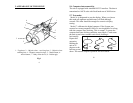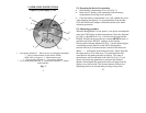
2. APPEARANCE OF THE DEVICE
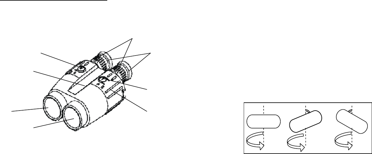
1 – Eyepieces; 2 – Objective lens – receiving lens; 3 – Objective lens -
emitting lens; 4 – Dioptric correction rings; 5 – Mode button; 6 –
Action button; 7 – Body of the device; 8 – Rubber grip
Fig. 1
6
5.6. Computer interconnectivity
The unit is equipped with standard RS-232 interface. The data is
transmitted as ASCII code with fixed baud rate of 9600 bit/sec.
5.7. Test modes
Mode 16 is designated to test the display. When you choose
this mode all segments and indicators will flash during 8
seconds. This time should be enough for extensive display
testing.
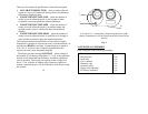
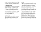
Mode 17 calibrates the digital compass. If the System was
exposed to a strong magnetic field or it was inoperable for a long
time the compass stops working. This is normal. To return the
compass back into working condition, enter Mode 17 and rotate
the unit several times around vertical axle, holding it
horizontally.
Repeat this
operation,
holding the
unit at 45
degrees to the
horizon up and
down. The normal compass operation will be restored.
19
2
3
4
5
6
7
1
8
360
°
360
°
45
°
360
°
45
°


