


5
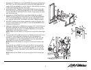
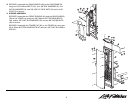
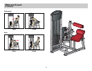
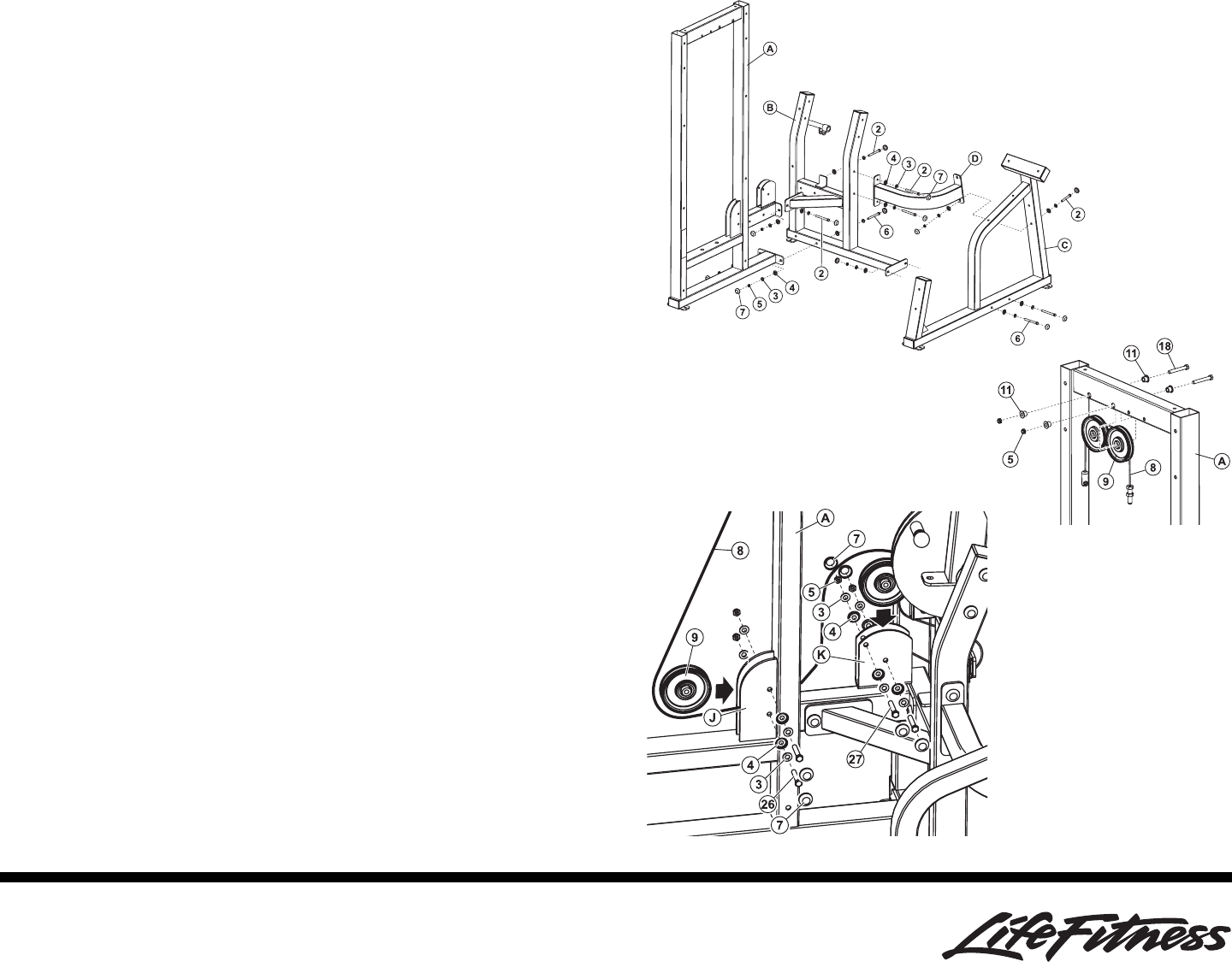
1. Assemble the TOWER (A) to the CAM FRAME (B) using two 3/8 X 92mm
BOLTS (6), four 3/8 X 67mm BOLTS (2), twelve 3/8" SAE WASHERS (3),
twelve 3/8" RH WASHERS (4), six 3/8" LOW HT LOCK NUTS (5) as shown.
Finger tighten the bolts and nuts at this time.
2. Assemble the SEAT FRAME (C) to the CAM FRAME (B) using two 3/8 X
92mm BOLTS (6), four 3/8" SAE WASHERS (3), four 3/8" RH WASHERS
(4), two 3/8" LOW HT LOCK NUTS (5) as shown. Finger tighten the bolts
and nuts at this time.
3. Assemble the CROSS BRACE (D) to the CAM FRAME (B) and SEAT
FRAME (C) using three 3/8 X 67mm BOLTS (2), six 3/8" SAE WASHERS
(3), six 3/8" RH WASHERS (4), three 3/8" LOW HT LOCK NUTS (5). Use
only one 3/8 X 67mm BOLT at the back of the SEAT FRAME as shown.
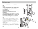
4. SECURELY tighten all loose frame connections made to this point, then
proceed to snap twenty-two RH CAPS (7) over the RH WASHERS (4) on
all tightened connections.
5. Wrap the threaded end of CABLE (8) around two 4-1/2" PULLEYS (9) and
SECURELY assemble the PULLEYS to the TOWER (A) using two 3/8 X
63mm BOLTS (18), four 3/8 X 1/2" FLANGE SPACERS (11) and two 3/8"
LOW HEIGHT LOCK NUTS (5) as shown.
NOTE: Make sure the CABLE is in the groove of the PULLEY before tight-
ening.
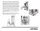
6. Route the ball end of CABLE (8) through the TOWER (A) and around one 4-
1/2" PULLEY (9) and SECURELY assemble the PULLEY between the
PLATES (J) on the TOWER using two 3/8 X 49mm BOLTS (26), four 3/8"
SAE WASHERS (3), four 3/8" RH WASHERS (4), two 3/8" LOW HEIGHT
LOCK NUTS (5) and four RH CAPS (7) as shown.
NOTE: Make sure the CABLE is in the groove of the PULLEY before tight-
ening.
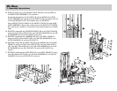
Wrap the ball end of CABLE around one 4-1/2" PULLEY (9) and securely
assemble the PULLEY between the U-BRACKET (K) on the TOWER using
two 3/8 X 43mm BOLTS (27), four 3/8" SAE WASHERS (3), four 3/8" RH
WASHERS (4), two 3/8" LOW HEIGHT LOCK NUTS (5) and four RH CAPS
(7) as shown.
NOTE: Make sure the CABLE is in the groove of the PULLEY before tight-
ening.