FIGURE 17
14
STEP 17:
0
1
2
345
6
1/2 1/2 1/2 1/2 1/2 1/2
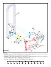
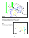
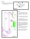
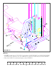
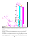
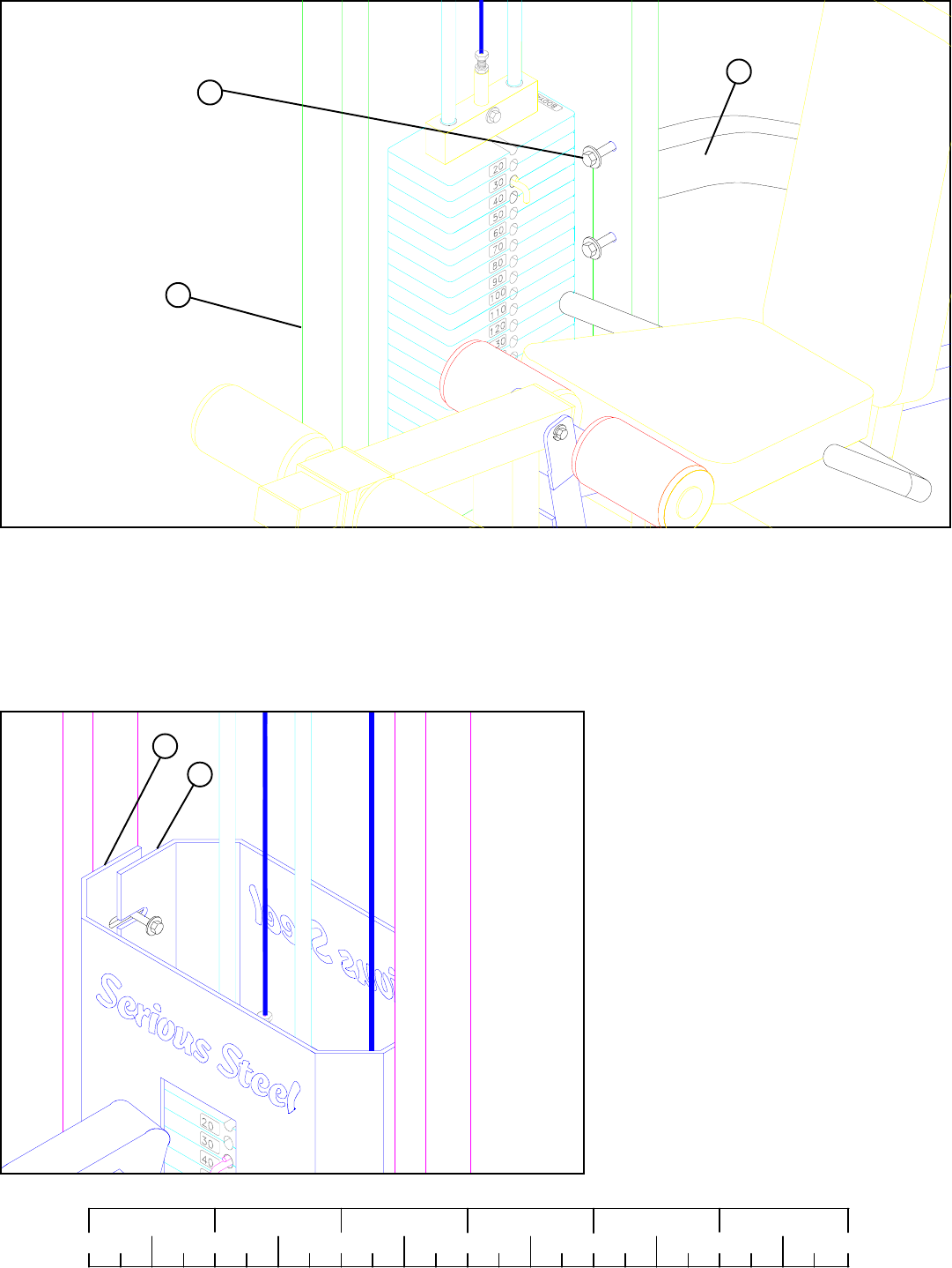
• Loosen the two 1/2 X 3” BOLTS (34) holding the UPPER CROSS SUPORT (11) to the TOWER (1) as shown in FIGURE 17.
16
STEP 18:
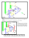
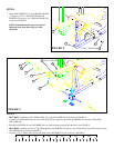
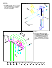
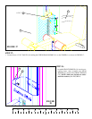
• Assemble FRONT SHROUD (16) over the pro-
truding bolts, then assemble the REAR
SHROUD (17) inside of the FRONT SHROUD
(16). (NOTE: Make sure shrouds are under-
neath the washers.) See FIGURE 18.
17
1/2 X 3” 34
11
1
FIGURE
18


