


www.ironmanfitness.com
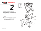
Important Information 11Assembly
5
N6
A9
N10
A38
A11
J-R
J1
Use Tool
3mm
Use Tool
5mm
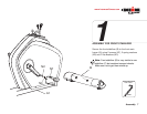
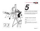
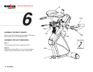
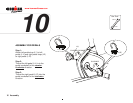
ASSEMBLY FOR SEAT SLIDE ADJUSTMENT
Insert the seat slide adjustment handle (A11) into the
seat slide adjsutment collar on the seat slide assem-
bly (A9). Secure it with M6 set screw (N10).
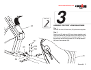
ASSEMBLY FOR RIGHT HANDLEBAR
Step 1:
Connect pulse wire (J1) and pulse wire (A3).
Step 2:
Mount the right handlebar (J-R), to the seat slide
assembly (A9) and secure with 3 allen screws
(N6).