


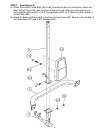
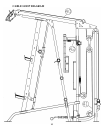
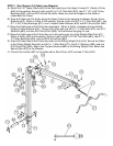
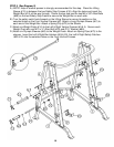
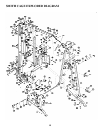
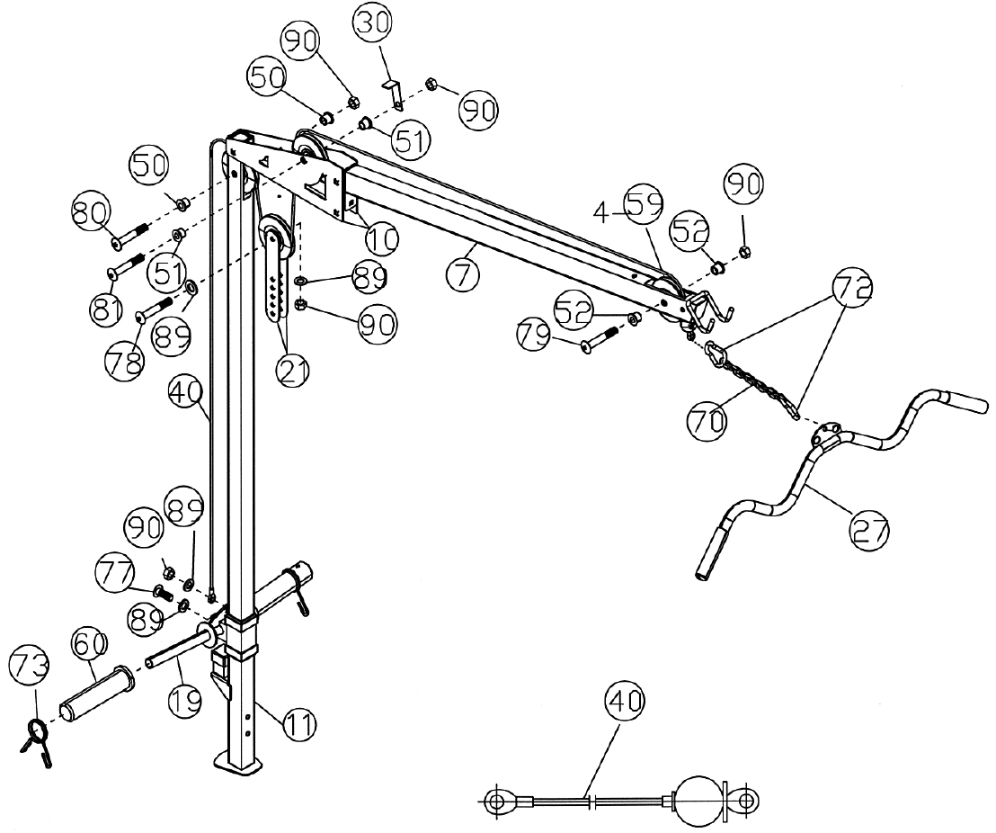
STEP 5 (See Diagram 5 & Cable Loop Diagram)
A.) Attach the 142” Upper Cable (#40) to the front opening on the Upper Frame (#7). Attach a Pulley
(#59) to the opening. Secure it with one M10 x 2 1/8” Allen Bolt (#79), two Ø 1 1/8” x 3/8” Pulley
Bushings (#52), and one M10 Aircraft Nut (#90). Make sure the ball stopper on the Cable is
underneath the Frame.
B.) Draw the Cable over the Pulley along the Upper Frame to the opening in between the two Cover
Brackets (#10). Attach a Pulley to the opening. Secure it with one M10 x 2 ½” Allen Bolt (#81), two
Ø 1” x 5/8” Pulley Bushings (#51), one L-shaped Cable Retainer (#30) and M10 Aircraft Nut (#90).
C.) Draw the Cable around the Pulley then downward. Attach a Pulley in between the two Double
Floating Pulley Brackets (#21). Secure the Pulley with one M10 x 1 ¾” Allen Bolt (#78), two Ø ¾”
Washers (#89), and one M10 Aircraft Nut (#90). Let the Bracket hanging for now.
D.) Draw the Cable around the Pulley then up to the opening on top of the Weight Glide Post (#11).
Attach a Pulley (#59) to the opening. Secure it with one M10 x 2 3/8” Allen Bolt (#80), two Ø 1” x
½” Pulley Bushings (#50), and one M10 Aircraft Nut (#90).
E.) Draw the Cable around the Pulley then down to the Sliding Weight Post (#19). Secure the Cable
to the Sliding Weight Post with one M10 x 1” Allen Bolt (#77), two Ø ¾” Washers (#89), and one
M10 Aircraft Nut (#90). Attach two Olympic Sleeves (#60) to the Sliding Weight Post. Attach two
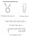
Spring Clips (#73) to the Sleeves.
F.) Connect the Lat Bar (#27) to the Cable with a Short Chain (#70) and two C-Clips (#72).
14