


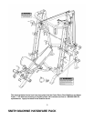
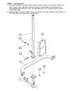
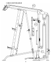
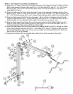
STEP 3 (See Diagram 3)
A.) Attach the Weight Glide Post (#11) to the bracket on the Vertical Frame Base
(#9). Secure it with one 3 1/8” x 1 ¾” Bracket (#31), M10 x 2 ½” Carriage Bolt
(#84), Ø ¾” Washer (#89), and M10 Aircraft Nut (#90) to the upper hole, one
M10 x 2 ½” Allen Bolt (#81) and one Ø ¾” Washer (#89) to the lower hole.
B.) Slide the Sliding Weight Post (#19) onto the Weight Glide Post (#11)) from the
top. Make sure the triangular cable connecting bracket on the Sliding Weight
Post faces up.
C.) Attach the Upper Frame (#7) onto the Front Top Beam (#5). Secure it with one
M10 x 4 ½” Allen Bolt (#82), two Ø ¾” Washers (#89), and one M10 Aircraft Nut
(#90).
D.) Attach the rear of the Upper Frame (#7) to the top of the Rear Vertical Frame
(#8). Secure it with one 4 3/8” x 1 ¾” Bracket (#34), M10 x 2 ½” Allen Bolt (#81),
and Ø ¾” Washer (#89) to the upper hole. Secure the bottom hole with one M10
x 2 ½” Carriage Bolt (#84), Ø ¾” Washer (#89), and M10 Aircraft Nut (#90).
E.) Attach the two Cover Brackets (#10) to the Rear Vertical Frame (#8) and Weight
Glide Post (#11) from both sides.
F.) Secure the Cover Brackets to the Rear Vertical Frame and Weight Glide Post
with four M10 x 2 ½” Carriage Bolts (#84), Ø ¾” Washers (#89), and M10 Aircraft
Nuts (#90).
G.) Securely tighten all Nuts and Bolts previously installed.
10