


8
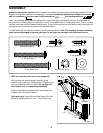
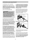
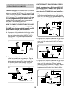
5. Set the Console (78) on the Left and Right Uprights (9,
10). Be careful not to pinch any wires. See drawing 4
above. Make sure that the Upright Wire Harness (17) is
not in the small cutout shown by the arrow.
Using the included 90° screwdriver and a phillips screw-
driver, attach the Console to the Uprights with six 3/4”
Screws (39). Start all six Screws before tightening
any of them; be careful not to overtighten the
Screws.
78
10
9
39
39
5
39
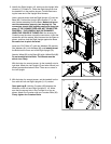
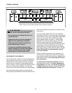
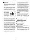
4. Cut the tie securing the upper end of the Upright Wire
Harness (17).
Have a second person hold the Console (78) near the
Right Upright (10). Attach the ground wire from the
Console to the Right Upright with the 1/2” Silver Screw
(107).
Connect the Upright Wire Harness (17) to the wire har-
ness on the Console (78). Make sure to connect the
connectors properly (see the inset drawing). The
connectors should slide together easily and snap
into place. IF THE CONNECTORS ARE NOT CON-
NECTED PROPERLY, THE CONSOLE MAY BE DAM-
AGED WHEN THE POWER IS TURNED ON. Insert the
connectors into the Console.
107
17
10
4
78
Ground
Wire
17
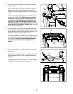
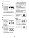
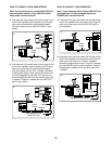
6. Lower the Uprights (9, 10) until the handrails are touch-
ing the floor.
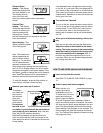
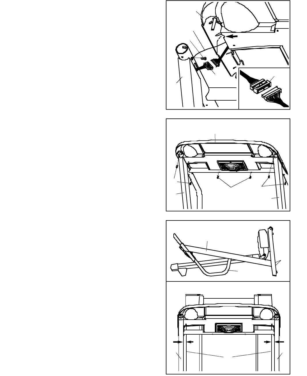
See the lower drawing. Position the Uprights (9, 10) so
that the treadmill Frame (12) is centered between the
Uprights.
Firmly tighten the four 2 3/4” Bolts (47). Then, raise the
Uprights (9, 10) back to the vertical position.
9
9, 10
Handrail
12
10
Top View
6
47