


6
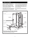
Before beginning assembly, carefully read the
following information and instructions:
• Assembly requires two people.
• Place all parts in a cleared area and remove the
packing materials. Do not dispose of the packing
materials until assembly is completed.
• Tighten all parts as you assemble them, unless
instructed to do otherwise.
• As you assemble the weight rack, make sure all
parts are oriented as shown in the drawings.
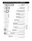
• For help identifying small parts, use the PART
IDENTIFICATION CHART on page 5.
The following tools (not included) are required
for assembly:
• Two adjustable wrenches
• One rubber mallet
• One standard screwdriver
• One Phillips screwdriver
• Lubricant, such as grease or petroleum jelly,
and soapy water.
Assembly will be more convenient if you have a
socket set, a set of open-end or closed-end
wrenches, or a set of ratchet wrenches.
Assembly
Make Things Easier for Yourself!
Everything in this manual is designed to ensure
that the weight rack can be assembled success-
fully by anyone. However, it is important to real-
ize that the versatile weight rack has many parts
and that the assembly process will take time.
Most people find that by setting aside plenty of
time, assembly will go smoothly.
1
1
27
27
27
27
31
31
29
29
3
2
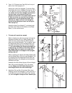
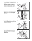
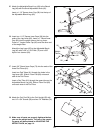
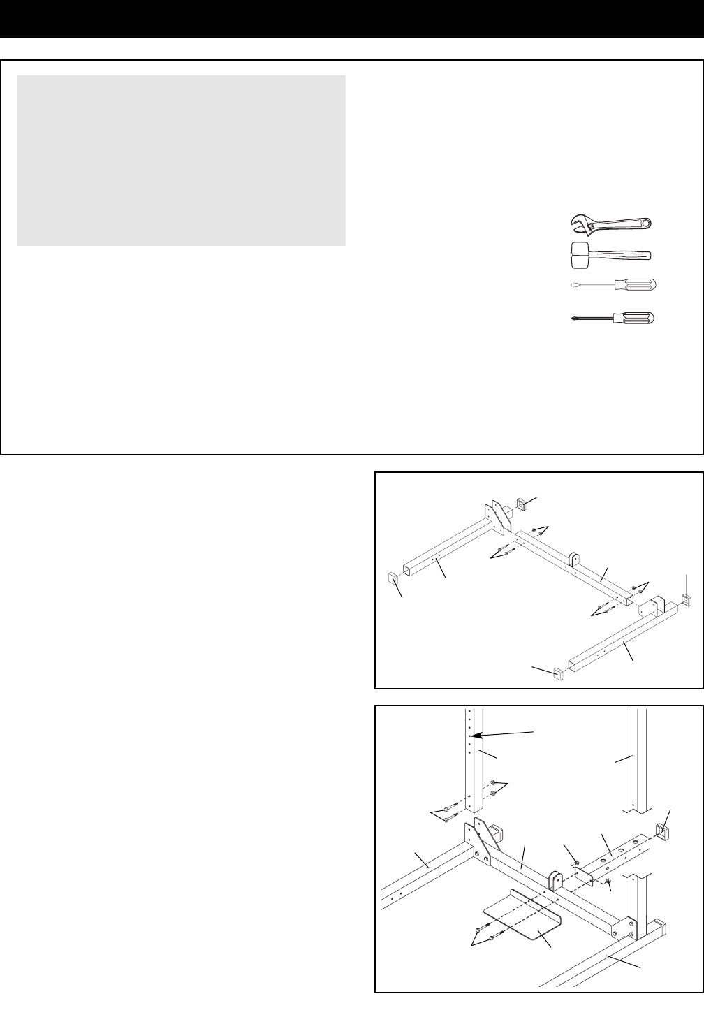
1. Press 2 1/2” Square Outer Caps (27) onto the ends
of the Right and Left Bases (1, 3).
Attach the Right and Left Bases (1, 3) to the Center
Base (2) using four 3/8” x 3 1/2” Bolts (31) and four
3/8” Nylon Lock Jamnuts (29). Do not tighten the
Nylon Lock Jamnuts yet.
2
1
2
5
31
31
29
29
29
4
3
27
8
Adjustment
Holes
8
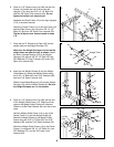
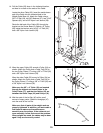
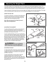
2. Identify the two Rear Uprights (8), which are slightly
shorter than the Front Uprights (not shown).
Attach the Rear Uprights (8) to the Left and Right
Bases (1, 3) using four 3/8” x 3 1/2” Bolts (31) and
four 3/8” Nylon Lock Jamnuts (29). Do not tighten
the Nylon Lock Jamnuts yet. Make sure the
Uprights are oriented exactly as shown, with the
adjustment holes on the indicated side near the
bottom.
Press a 2 1/2” Square Outer Cap (27) onto the end
of the Weight Guide Base (4).
Orient the Foot Plate (5) and the Weight Guide Base
(4) as shown. Attach the Foot Plate and the Weight
Guide Base to the Center Base (2) using two 3/8” x
3 1/2” Bolts (31) and two 3/8” Nylon Lock Jamnuts
(29). Do not tighten the Nylon Lock Jamnuts yet.