


11
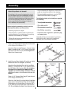
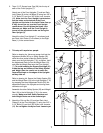
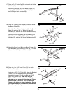
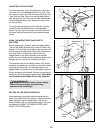
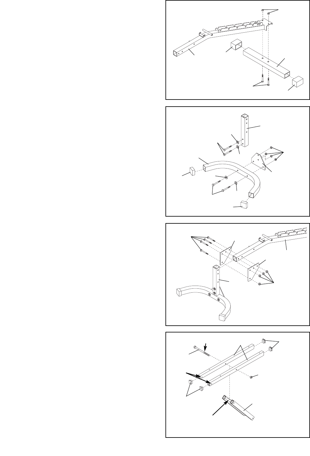
17. Press a 3” x 2” Outer Cap (56) onto each end of the
Stabilizer (58).
Attach the Stabilizer (58) to the Bench Frame (52)
with two 3/8” x 2 3/4” Button Head Bolts (57) and
two 3/8” Nylon Lock Jamnuts (29).
17
57
56
29
52
58
56
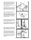
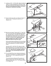
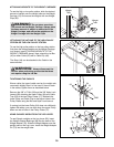
18. Press a 2” Square Outer Cap (65) onto each end of
the Bench Base (53).
Attach the Bench Base Joint Plate (64) to the Bench
Base (53) with two 3/8” x 3” Bolts (34), two 3/8”
Washers (37), and two 3/8” Nylon Lock Jamnuts (29).
Attach the Bench Leg (48) to the Bench Base Joint
Plate (64) with two 3/8” x 3” Bolts (34), two 3/8”
Washers (37), and two 3/8” Nylon Lock Jamnuts (29).
18
34
37
37
34
37
37
48
29
64
65
65
53
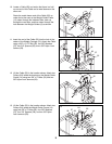
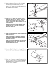
19. Attach the Bench Leg (48) to the Bench Frame (52)
with two Bench Joint Plates (63), four 3/8” x 3” Bolts
(34), and four 3/8” Nylon Lock Jamnuts (29).
19
48
29
63
52
34
63
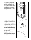
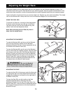
20. Press two 1” x 1 1/2“ Inner Caps (72) into each
Backrest Tube (71).
Lubricate a 3/8” x 7 1/2” Bolt (66). Attach the Backrest
Tubes (71) to the welded tube on the Backrest
Adjustment Bracket (79) with the Bolt and a 3/8”
Nylon Lock Jamnut (29). Make sure that the
Backrest Tubes are turned as shown. The indicat-
ed holes are not centered in the Backrest Tubes
but are closer to one side. Turn the Backrest
Tubes so the holes are closer to the floor. Do not
overtighten the Nylon Lock Jamnut; the Backrest
Tubes must pivot easily.
20
72
29
79
Lubricate
Holes
Welded
Tube
72
66
71