


ASSEMBLY
INSTRUCTIONS
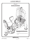
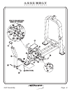
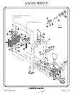
FRAME ASSEMBLY
In this step, you will attach (30) and (7) to (8). Mount (CB) to (1) and (8)
before attaching (9) and (8) to the bottom of (1). Next attach (5), (11), (44),
(CH), and (10) to (1). bolts only, they will be tightened later.Hand Tighten
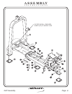
Step 2b
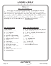
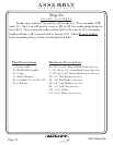
1 - Seat Assembly
5 - Shaft
7 - 2”x 4” End Cap
8 - Back Adjuster Assembly
9 - Shaft
10 - Back Adjuster Assembly
11 - Pull Pin
30 - Adjustable Plate
44 - Pull Pin to Chain Link Connector
(1/2 Dia. x 1.240 LG.)
(HH)
(3/4”Dia. x 4 27/32 LG.)
(Long)
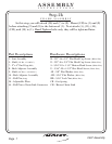
Part Descriptions
D - 3/8”-16 x 1/2” Flat Head Cap Screw
E - 3/8”-16 x 3/4” Flat Head Cap Screw
S - 5/16”-18 x 1 1/4” Button Head Screw
U - 5/16”-18 x 4 1/2” Hex Head Screw
AE - 3/8” Flat Washer
AM - 5/16” Flat Washer
BD - 5/16” Lock Nut
CB - Gas Spring
CH - Master Chain Link
(White Zinc)
(White Zinc)
(White Zinc)
(White Zinc)
(White Zinc)
(White Zinc)
(White Zinc)
Hardware Descriptions
FITNESS SYSTEMS
R
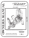
HOIST
2407 Assembly
Page 7