


ASSEMBLY
INSTRUCTIONS
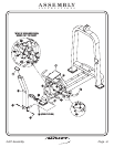
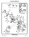
FRAME ASSEMBLY
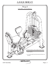
Step 2a
FITNESS SYSTEMS
R
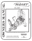
HOIST
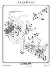
1 - Seated Assembly
2 - Weight Cage
3 - Rubber Foot Pad
4 - 2”x 4” End Caps
6 - Shaft
(VH)
(1/2”Dia. x 1.240 LG.)
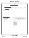
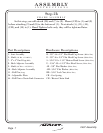
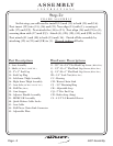
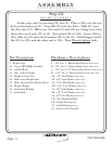
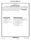
Part Descriptions
A - 1/2”-13 x 1 1/2” Button Head Screw
B - 5/16”-18 x 2” Button Head Screw
AA - 1/2” Lock Washer
AB - 1/2” Flat Washer
AM - 5/16” Flat Washer
CA - Plug Bumper
CG - Insert 1/2”
CP - Insert 3/8”
CT - 3/4” Olite
(White Zinc)
(White Zinc)
(White Zinc)
(White Zinc)
(White Zinc)
Hardware Descriptions
2407 Assembly
Page 5
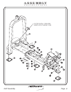
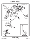
( ) Insert (CG) and (CP) into (1) and (2). Attach
(1) to (2). Then insert (6) into (1). Next attach (CA) and (4) to the rear
of (1). bolts only, they will be tightened later. Lift machine
to position (3).
Factory Installation
Hand tighten