


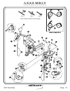
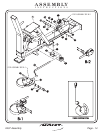
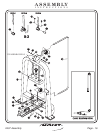
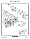
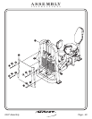
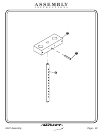

In this step, you will attach (32) to (8) and (33) to (1). Next attach
(34) and (35) to (15). Then attach (37) and (36) to (16). Next slide (43),
(52), (42) or (57) onto the handles located on (1) and secure. Slide (43),
(53), (42) or (57) onto (20) and secure. Attach (56) to (49).
bolts.
Wrench
tighten
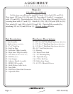
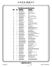
1 - Seat Assembly
8 - Back Adjuster Assembly
10 - Back Adjuster Assembly
15 - Left Inner Thigh Assembly
16 - Right Inner Thigh Assembly
20 - Adjuster Handle Assembly
32 - Back Upholstery Assembly
33 - Seat Upholstery Assembly
34 - Left Knee Upholstery
35 - Left Knee Backing
36 - Right Knee Backing
37 - Right Knee Upholstery
38 - Rubber Grip
42 - Aluminum End Cap
43 - Aluminum Ring
49 - 6.50 x 20 Foot Plate
52 - Rubber Grip
53 - Rubber Grip
56 - Rubberized Non-Skid
57 - Aluminum End Cap
(5 1/2” LG.)
(11 9/16” LG.)
(4” LG.)
(4” x 18”)
(Red)
Part Descriptions
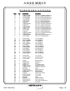
L - 5/16”-18 x 3” Button Head Screw
S - 5/16”-18 x 1 1/4” Button Head Screw
T - 10-32 x 1/8 Set Screw
V - 3/8”-16 x 1” Flat Head Cap Screw
AM - 5/16” Flat Washer
AN - 5/16” Lock Washer
(White Zinc)
(White Zinc)
(White Zinc)
(White Zinc)
(White Zinc)
Hardware Descriptions
FRAME ASSEMBLY
Step 2g
FITNESS SYSTEMS
R
HOIST
2407 Assembly
Page 17